Toyota 4Runner: Removal
REMOVAL
PROCEDURE
1. REMOVE JACK BOX HOLE COVER
.gif)
2. REMOVE REAR QUARTER PANEL MUDGUARD LH
3. REMOVE REAR QUARTER PANEL MUDGUARD RH
HINT:
Use the same procedure as for the LH side.
4. REMOVE REAR BUMPER COVER
5. REMOVE NO. 3 FLOOR WIRE
6. REMOVE NO. 1 ULTRASONIC SENSOR
|
(a) Detach the 2 claws to remove the No. 1 ultrasonic sensor from the ultrasonic sensor retainer. HINT: Use the same procedure as for the other side. |
|
.png)
7. REMOVE ULTRASONIC SENSOR CLIP
|
(a) Using a screwdriver, detach the claw to remove the ultrasonic sensor clip from the No. 1 ultrasonic sensor as shown in the illustration. Text in Illustration
HINT:
|
|
.png)
8. REMOVE NO. 2 ULTRASONIC SENSOR RETAINER
|
(a) Detach the 3 claws to remove the No. 2 ultrasonic sensor retainer from the rear bumper cover. HINT: Use the same procedure as for the other side. |
|
.png)
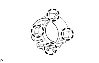
9. REMOVE NO. 1 ULTRASONIC SENSOR RETAINER
|
(a) Detach the 4 claws to remove the No. 1 ultrasonic sensor retainer from the rear bumper cover. HINT: Use the same procedure as for the other side. |
|
 Components
COMPONENTS
ILLUSTRATION
ILLUSTRATION
...
 Inspection
INSPECTION
PROCEDURE
1. INSPECT NO. 1 ULTRASONIC SENSOR
(a) Measure the resistance according to the value(s) in the table below.
Standard Resistance:
Tester Connection
Co ...
Other materials about Toyota 4Runner:
Theft Deterrent System Communication Line High Fixation (B279A)
DESCRIPTION
If the communication line (EFIO-IMI) to the ID code box is stuck on HI output,
the ECM stores this DTC.
DTC Code
DTC Detection Condition
Trouble Area
B279A
The communication line (EFI ...
Telephone Microphone Error (B1572)
DESCRIPTION
This DTC is stored when the DCM (Telematics Transceiver) detects a malfunction
in the telephone microphone assembly circuit.
DTC Code
DTC Detection Condition
Trouble Area
B1572
Curren ...

0.0088