Toyota 4Runner: Back Camera Disconnected (C1622)
DESCRIPTION
This DTC is stored if the radio and display receiver assembly judges that the signals or signal lines between the radio and display receiver assembly, and the rear television camera assembly are not normal as a result of its self check.
|
DTC No. |
Detection Item |
DTC Detection Condition |
Trouble Area |
|---|---|---|---|
|
C1622 |
Back Camera Disconnected |
Open or short in the rear television camera assembly signal circuit |
|
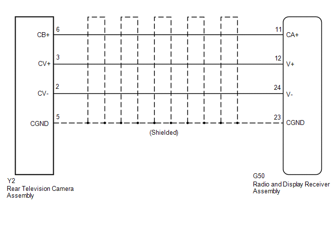
WIRING DIAGRAM
PROCEDURE
|
1. |
CHECK HARNESS AND CONNECTOR (RADIO AND DISPLAY RECEIVER ASSEMBLY - REAR TELEVISION CAMERA ASSEMBLY) |
(a) Disconnect the G50 radio and display receiver assembly connector.
(b) Disconnect the Y2 rear television camera assembly connector.
(c) Measure the resistance according to the value(s) in the table below.
Standard Resistance (Check for Open):
|
Tester Connection |
Condition |
Specified Condition |
|---|---|---|
|
G50-11 (CA+) - Y2-6 (CB+) |
Always |
Below 1 Ω |
|
G50-12 (V+) - Y2-3 (CV+) |
Always |
Below 1 Ω |
|
G50-23 (CGND) - Y2-5 (CGND) |
Always |
Below 1 Ω |
|
G50-24 (V-) - Y2-2 (CV-) |
Always |
Below 1 Ω |
Standard Resistance (Check for Short):
|
Tester Connection |
Condition |
Specified Condition |
|---|---|---|
|
G50-11 (CA+) - Body ground |
Always |
10 kΩ or higher |
|
G50-12 (V+) - Body ground |
Always |
10 kΩ or higher |
|
G50-23 (CGND) - Body ground |
Always |
10 kΩ or higher |
|
G50-24 (V-) - Body ground |
Always |
10 kΩ or higher |
| NG | .gif) |
REPAIR OR REPLACE HARNESS OR CONNECTOR |
|
.gif)
|
2. |
INSPECT RADIO AND DISPLAY RECEIVER ASSEMBLY |
|
(a) Reconnect the G50 radio and display receiver assembly connector. |
|
(b) Measure the resistance according to the value(s) in the table below.
Standard Resistance:
|
Tester Connection |
Condition |
Specified Condition |
|---|---|---|
|
G50-23 (CGND) - Body ground |
Always |
Below 1 Ω |
|
G50-24 (V-) - Body ground |
Always |
Below 1 Ω |
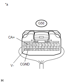
(c) Measure the voltage according to the value(s) in the table below.
Standard Voltage:
|
Tester Connection |
Condition |
Specified Condition |
|---|---|---|
|
G50-11 (CA+) - G50-23 (CGND) |
Ignition switch ACC |
5.5 to 7.05 V |
| NG | |
REPLACE RADIO AND DISPLAY RECEIVER ASSEMBLY |
|
|
3. |
INSPECT REAR TELEVISION CAMERA ASSEMBLY |
(a) Reconnect the Y2 rear television camera assembly connector.
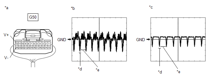
(b) Check the waveform of the rear television camera assembly using an oscilloscope.
HINT:
A waterproof connector is used for the rear television camera assembly. Therefore, inspect the waveform at the radio and display receiver assembly with the connector connected.
|
*a |
Component with harness connected (Radio and Display Receiver Assembly) |
*b |
Waveform 1 (under normal conditions) |
|
*c |
Waveform 2 (camera lens is covered, blacking out the screen) |
*d |
Synchronized Signal |
|
*e |
Video Waveform |
- |
- |
OK:
Waveform is as shown in the illustration.
|
Item |
Content |
|---|---|
|
Terminal No. (Symbol) |
G50-12 (V+) - G50-24 (V-) |
|
Tool Setting |
200 mV/DIV., 50 μsec./DIV. |
|
Condition |
Ignition switch ON, shift lever in R |
HINT:
The video waveform changes according to the image sent by the rear television camera assembly.
| OK | |
REPLACE RADIO AND DISPLAY RECEIVER ASSEMBLY |
| NG | |
REPLACE REAR TELEVISION CAMERA ASSEMBLY |
 Diagnostic Trouble Code Chart
DIAGNOSTIC TROUBLE CODE CHART
Rear View Monitor System
DTC No.
Detection Item
Link
C1622
Back Camera Disconnected
...
 Image from Camera for Rear View Monitor is Abnormal
DESCRIPTION
The display signal from the rear television camera assembly transmits to the
radio and display receiver assembly.
WIRING DIAGRAM
PROCEDURE
1.
CHECK HARNESS A ...
Other materials about Toyota 4Runner:
Turn signal lever
The turn signal lever can be used to show the following intentions of the
driver:
1. Right turn 2. Left turn 3. Lane change to the right (push and hold the
lever partway) The right hand signals will flash until you release the lever.
4. Lane change to ...
Removal
REMOVAL
PROCEDURE
1. REMOVE NO. 1 INSTRUMENT CLUSTER FINISH PANEL GARNISH
(a) Put protective tape around the No. 1 instrument cluster finish panel garnish.
(b) Grip the No. 1 instrument cluster finish panel garnish and pull it diagonally
upward toward th ...

0.0264