Toyota 4Runner: Image from Camera for Rear View Monitor is Abnormal
DESCRIPTION
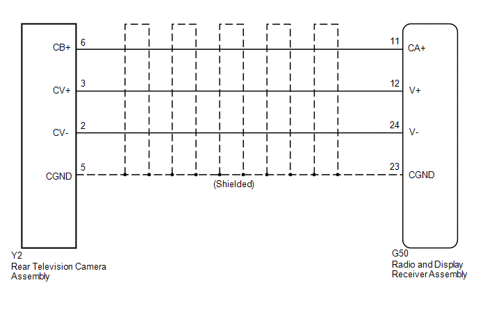
The display signal from the rear television camera assembly transmits to the radio and display receiver assembly.
WIRING DIAGRAM
PROCEDURE
|
1. |
CHECK HARNESS AND CONNECTOR (RADIO AND DISPLAY RECEIVER ASSEMBLY - REAR TELEVISION CAMERA ASSEMBLY) |
(a) Disconnect the G50 radio and display receiver assembly connector.
(b) Disconnect the Y2 rear television camera assembly connector.
(c) Measure the resistance according to the value(s) in the table below.
Standard Resistance (Check for Open):
|
Tester Connection |
Condition |
Specified Condition |
|---|---|---|
|
G50-11 (CA+) - Y2-6 (CB+) |
Always |
Below 1 Ω |
|
G50-12 (V+) - Y2-3 (CV+) |
Always |
Below 1 Ω |
|
G50-23 (CGND) - Y2-5 (CGND) |
Always |
Below 1 Ω |
|
G50-24 (V-) - Y2-2 (CV-) |
Always |
Below 1 Ω |
Standard Resistance (Check for Short):
|
Tester Connection |
Condition |
Specified Condition |
|---|---|---|
|
G50-11 (CA+) - Body ground |
Always |
10 kΩ or higher |
|
G50-12 (V+) - Body ground |
Always |
10 kΩ or higher |
|
G50-23 (CGND) - Body ground |
Always |
10 kΩ or higher |
|
G50-24 (V-) - Body ground |
Always |
10 kΩ or higher |
| NG | .gif) |
REPAIR OR REPLACE HARNESS OR CONNECTOR |
|
.gif)
|
2. |
INSPECT RADIO AND DISPLAY RECEIVER ASSEMBLY |
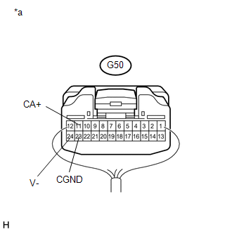
(a) Reconnect the G50 radio and display receiver assembly connector.
(b) Measure the resistance according to the value(s) in the table below.
Standard Resistance:
|
Tester Connection |
Condition |
Specified Condition |
|---|---|---|
|
G50-23 (CGND) - Body ground |
Always |
Below 1 Ω |
|
G50-24 (V-) - Body ground |
Always |
Below 1 Ω |
(c) Measure the voltage according to the value(s) in the table below.
Standard Voltage:
|
Tester Connection |
Condition |
Specified Condition |
|---|---|---|
|
G50-11 (CA+) - G50-23 (CGND) |
Ignition switch ACC |
5.5 to 7.05 V |
|
*a |
Component with harness connected (Radio and Display Receiver Assembly) |
| NG | |
REPLACE RADIO AND DISPLAY RECEIVER ASSEMBLY |
|
|
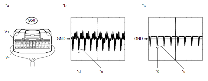
3. |
INSPECT REAR TELEVISION CAMERA ASSEMBLY |
(a) Reconnect the Y2 rear television camera assembly connector.
(b) Check the waveform of the rear television camera assembly using an oscilloscope.
HINT:
A waterproof connector is used for the rear television camera assembly. Therefore, inspect the waveform at the radio and display receiver assembly with the connector connected.
 Text in Illustration
|
*a |
Component with harness connected (Radio and Display Receiver Assembly) |
*b |
Waveform 1 (under normal conditions) |
|
*c |
Waveform 2 (camera lens is covered, blacking out the screen) |
*d |
Synchronized Signal |
|
*e |
Video Waveform |
- |
- |
OK:
Waveform is as shown in the illustration.
|
Item |
Content |
|---|---|
|
Terminal No. (Symbol) |
G50-12 (V+) - G50-24 (V-) |
|
Tool Setting |
200 mV/DIV., 50 μsec./DIV. |
|
Condition |
Ignition switch ON, shift lever in R |
HINT:
The video waveform changes according to the image sent by the rear television camera assembly.
| OK | |
PROCEED TO NEXT SUSPECTED AREA SHOWN IN PROBLEM SYMPTOMS TABLE |
| NG | |
REPLACE REAR TELEVISION CAMERA ASSEMBLY |
 Back Camera Disconnected (C1622)
DESCRIPTION
This DTC is stored if the radio and display receiver assembly judges that the
signals or signal lines between the radio and display receiver assembly, and the
rear television camera a ...
 Television Camera(for Rear)
Components
COMPONENTS
ILLUSTRATION
Removal
REMOVAL
PROCEDURE
1. REMOVE ASSIST STRAP HOLE COVER
2. REMOVE ASSIST STRAP ASSEMBLY
3. REMOVE BACK DOOR TRIM PANEL ASSEMBLY
4. REMOVE ...
Other materials about Toyota 4Runner:
Inspection
INSPECTION
PROCEDURE
1. INSPECT REAR NO. 1 SEAT OUTER BELT ASSEMBLY
(a) Check the ELR.
(1) When the inclination of the retractor is 15° or less, check that
the belt can be pulled from the retractor. When the inclination of the retractor
...
Accessory Meter
Components
COMPONENTS
ILLUSTRATION
Removal
REMOVAL
PROCEDURE
1. DISCONNECT CABLE FROM NEGATIVE BATTERY TERMINAL
CAUTION:
Wait at least 90 seconds after disconnecting the cable from the negative (-)
battery terminal to disable the SRS system.
N ...

0.0108