Toyota 4Runner: Back Door Courtesy Switch Circuit
DESCRIPTION
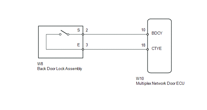
The multiplex network door ECU receives a back door open/closed signal from the back door lock.
WIRING DIAGRAM
PROCEDURE
|
1. |
READ VALUE USING TECHSTREAM (BACK DOOR COURTESY LIGHT SWITCH) |
(a) Using the Techstream, read the Data List (See page
.gif) ).
).
Back Door
|
Tester Display |
Measurement Item/Range |
Normal Condition |
Diagnostic Note |
|---|---|---|---|
|
Back Door Courtesy Switch |
Back door courtesy light switch signal / ON or OFF |
ON: Back door open OFF: Back door closed |
- |
OK:
Tester display changes according to opening and closing of back door.
| OK | .gif) |
PROCEED TO NEXT SUSPECTED AREA SHOWN IN PROBLEM SYMPTOMS TABLE |
|
.gif)
|
2. |
INSPECT BACK DOOR LOCK ASSEMBLY (BACK DOOR COURTESY LIGHT SWITCH) |
(a) Remove the back door lock (See page ).
.png)
(b) Measure the resistance according to the value(s) in the table below.
Standard Resistance:
|
Tester Connection |
Condition |
Specified Condition |
|---|---|---|
|
2 - 3 |
Open-latch |
Below 1 Ω |
|
Full-latch |
10 kΩ or higher |
.png) |
Full-latch |
.png) |
Open-latch |
| NG | |
REPLACE BACK DOOR LOCK ASSEMBLY |
|
|
3. |
CHECK HARNESS AND CONNECTOR (BACK DOOR LOCK ASSEMBLY - MULTIPLEX NETWORK DOOR ECU) |
(a) Disconnect the W8 back door lock connector.
(b) Disconnect the W10 multiplex network door ECU connector.
(c) Measure the resistance according to the value(s) in the table below.
Standard Resistance:
|
Tester Connection |
Condition |
Specified Condition |
|---|---|---|
|
W8-2 (S) - W10-10 (BDCY) |
Always |
Below 1 Ω |
|
W8-2 (S) - Body ground |
Always |
10 kΩ or higher |
|
W8-3 (E) - W10-18 (CTYE) |
Always |
Below 1 Ω |
|
W8-3 (E) - Body ground |
Always |
10 kΩ or higher |
| OK | |
REPLACE MULTIPLEX NETWORK DOOR ECU |
| NG | |
REPAIR OR REPLACE HARNESS OR CONNECTOR |
 IG Signal Circuit
DESCRIPTION
This circuit detects the ignition switch ON or off condition, and sends it to
the main body ECU.
WIRING DIAGRAM
CAUTION / NOTICE / HINT
NOTICE:
Inspect the fuses for circuits rela ...
 Door Courtesy Switch Circuit
DESCRIPTION
The main body ECU (multiplex network body ECU) receives a door open/closed signal
from each door courtesy light switch.
WIRING DIAGRAM
PROCEDURE
1.
READ VALU ...
Other materials about Toyota 4Runner:
Evaporator Temperature Sensor Circuit (B1413)
DESCRIPTION
The No. 1 cooler thermistor is installed on the evaporator in the air conditioning
unit to detect the temperature of the cooled air that has passed through the evaporator
and control the air conditioning. It sends appropriate signals to the No ...
Installation
INSTALLATION
CAUTION / NOTICE / HINT
HINT:
A bolt without a torque specification is shown in the standard bolt chart (See
page ).
PROCEDURE
1. INSTALL INSTRUMENT PANEL REINFORCEMENT ASSEMBLY
(a) Attach the 2 claws to install the instrument panel reinf ...

0.0068