Toyota 4Runner: IG Signal Circuit
DESCRIPTION
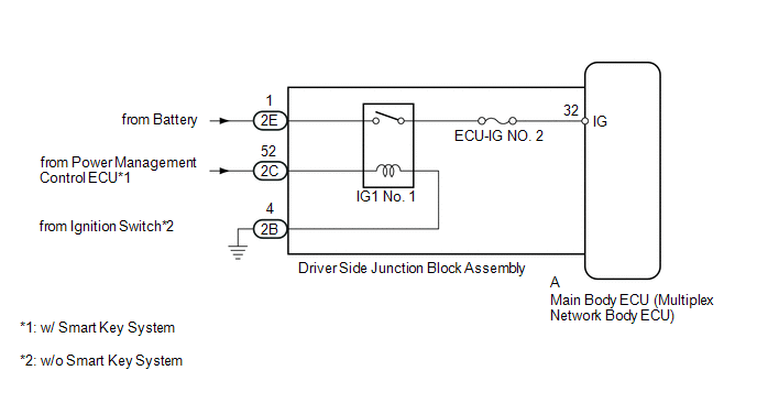
This circuit detects the ignition switch ON or off condition, and sends it to the main body ECU.
WIRING DIAGRAM
CAUTION / NOTICE / HINT
NOTICE:
Inspect the fuses for circuits related to this system before performing the following inspection procedure.
PROCEDURE
|
1. |
READ VALUE USING TECHSTREAM (IGNITION SWITCH) |
(a) Using the Techstream, read the Data List (See page
.gif) ).
).
Main Body
|
Tester Display |
Measurement Item/Range |
Normal Condition |
Diagnostic Note |
|---|---|---|---|
|
IG SW |
Ignition switch ON signal / ON or OFF |
ON: Ignition switch ON OFF: Ignition switch off |
- |
OK:
Normal conditions listed above are displayed.
| OK | .gif) |
PROCEED TO NEXT SUSPECTED AREA SHOWN IN PROBLEM SYMPTOMS TABLE |
|
.gif)
|
2. |
CHECK HARNESS AND CONNECTOR (BATTERY - MAIN BODY ECU) |
|
(a) Remove the main body ECU (See page
|
|
(b) Measure the voltage according to the value(s) in the table below.
Standard Voltage:
|
Tester Connection |
Switch Condition |
Specified Condition |
|---|---|---|
|
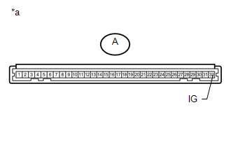
A-32 (IG) - Body ground |
Ignition switch ON |
11 to 14 V |
|
*a |
Front view of wire harness connector (to Main Body ECU) |
| OK | |
REPLACE MAIN BODY ECU (MULTIPLEX NETWORK BODY ECU) |
| NG | |
REPAIR OR REPLACE HARNESS OR CONNECTOR |
 ACC Signal Circuit
DESCRIPTION
This circuit detects the ignition switch ACC or off condition, and sends it to
the main body ECU.
WIRING DIAGRAM
CAUTION / NOTICE / HINT
NOTICE:
Inspect the fuses for circuits rel ...
 Back Door Courtesy Switch Circuit
DESCRIPTION
The multiplex network door ECU receives a back door open/closed signal from the
back door lock.
WIRING DIAGRAM
PROCEDURE
1.
READ VALUE USING TECHSTREAM (BACK ...
Other materials about Toyota 4Runner:
Automatic Disconnecting Differential Actuator
Components
COMPONENTS
ILLUSTRATION
Installation
INSTALLATION
PROCEDURE
1. INSTALL AUTOMATIC DISCONNECTING DIFFERENTIAL ACTUATOR
(a) Remove any old FIPG material.
NOTICE:
Be careful not to drop oil on the contact surfaces of the actuator and clut ...
Disassembly
DISASSEMBLY
PROCEDURE
1. REMOVE COOLER BRACKET
(a) Detach the clamp.
(b) Remove the screw and cooler bracket.
2. REMOVE MAGNET CLUTCH ASSEMBLY
(a) Clamp the cooler compressor in a vise.
(b) Using SST, hold the magnet clutch hub.
SST: 07112-76060
( ...

0.0078