Toyota 4Runner: Navigation Receiver Assembly Communication Stop Mode
DESCRIPTION
|
Detection Item |
Symptom |
Trouble Area |
|---|---|---|
|
Navigation Receiver Assembly Communication Stop Mode |
Either condition is met:
|
|
HINT:
For vehicles with a navigation receiver assembly only.
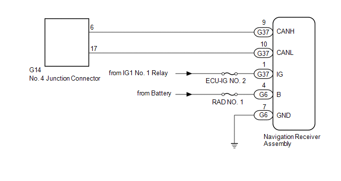
WIRING DIAGRAM
CAUTION / NOTICE / HINT
NOTICE:
Inspect the fuses for circuits related to this system before performing the following inspection procedure.
HINT:
Operating the ignition switch, any switches or any doors triggers related ECU and sensor communication with the CAN, which causes resistance variation.
PROCEDURE
|
1. |
DISCONNECT CABLE FROM NEGATIVE BATTERY TERMINAL |
(a) Disconnect the cable from the negative (-) battery terminal before measuring the resistances of the main wire and branch wire.
CAUTION:
Wait at least 90 seconds after disconnecting the cable from the negative (-) battery terminal to disable the SRS system.
NOTICE:
When disconnecting the cable, some systems need to be initialized after the cable
is reconnected (See page .gif) ).
).
|
.gif)
|
2. |
CHECK FOR OPEN IN CAN BUS WIRE (NAVIGATION RECEIVER ASSEMBLY BRANCH WIRE) |
|
(a) Disconnect the G37 navigation receiver assembly connector. |
|
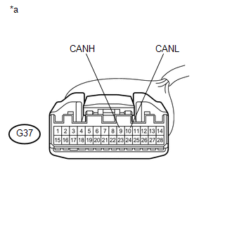
(b) Measure the resistance according to the value(s) in the table below.
Standard Resistance:
|
Tester Connection |
Switch Condition |
Specified Condition |
|---|---|---|
|
G37-9 (CANH) - G37-10 (CANL) |
Ignition switch off |
54 to 69 Ω |
|
*a |
Front view of wire harness connector (to Navigation Receiver Assembly) |
| NG | .gif) |
REPAIR OR REPLACE NAVIGATION RECEIVER ASSEMBLY BRANCH WIRE OR CONNECTOR (CANH, CANL) |
|
|
3. |
CHECK HARNESS AND CONNECTOR (NAVIGATION RECEIVER ASSEMBLY - BATTERY AND BODY GROUND) |
|
(a) Connect the cable to the negative (-) battery terminal. NOTICE: When disconnecting the cable, some systems need to be initialized after
the cable is reconnected (See page |
|
(b) Disconnect the G6 and G37 navigation receiver assembly connectors.
(c) Measure the resistance according to the value(s) in the table below.
Standard Resistance:
|
Tester Connection |
Condition |
Specified Condition |
|---|---|---|
|
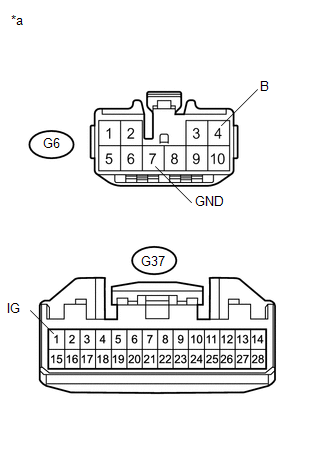
G6-7 (GND) - Body ground |
Always |
Below 1 Ω |
(d) Measure the voltage according to the value(s) in the table below.
Standard Voltage:
|
Tester Connection |
Condition |
Specified Condition |
|---|---|---|
|
G37-1 (IG) - Body ground |
Ignition switch ON |
11 to 14 V |
|
G6-4 (B) - Body ground |
Always |
11 to 14 V |
|
*a |
Front view of wire harness connector (to Navigation Receiver Assembly) |
| OK | |
REPLACE NAVIGATION RECEIVER ASSEMBLY |
| NG | |
REPAIR OR REPLACE HARNESS OR CONNECTOR |
 Suspension Control ECU Communication Stop Mode
DESCRIPTION
Detection Item
Symptom
Trouble Area
Suspension Control ECU Communication Stop Mode
Either condition is met:
&quo ...
 Audio Receiver Assembly Communication Stop Mode
DESCRIPTION
Detection Item
Symptom
Trouble Area
Audio Receiver Assembly Communication Stop Mode
Either condition is met:
&qu ...
Other materials about Toyota 4Runner:
How To Proceed With Troubleshooting
CAUTION / NOTICE / HINT
HINT:
Use these procedures to troubleshoot the smart key system.
*: Use the Techstream.
PROCEDURE
1.
VEHICLE BROUGHT TO WORKSHOP
NEXT
...
Disassembly
DISASSEMBLY
PROCEDURE
1. REMOVE FRONT SUSPENSION UPPER ARM BUSH LH
HINT:
Use the same procedure for the front and rear sides.
(a) Using a hammer and chisel, strike and bend the entire flange of the
upper arm bush as shown in the illustratio ...

0.0067