Toyota 4Runner: Hazard Warning Switch
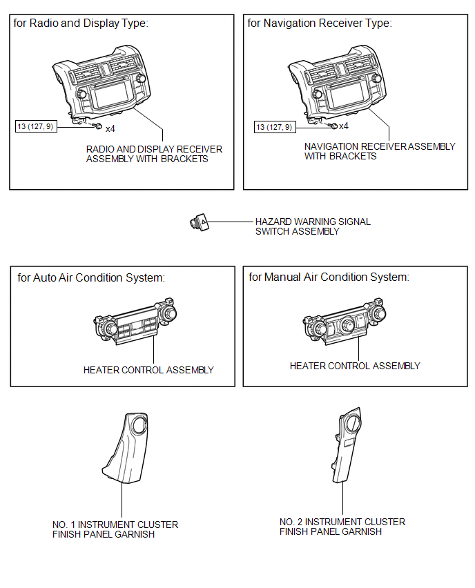
Components
COMPONENTS
ILLUSTRATION
Removal
REMOVAL
PROCEDURE
1. REMOVE NO. 1 INSTRUMENT CLUSTER FINISH PANEL GARNISH
.gif)
2. REMOVE NO. 2 INSTRUMENT CLUSTER FINISH PANEL GARNISH
3. REMOVE HEATER CONTROL ASSEMBLY
4. REMOVE RADIO AND DISPLAY RECEIVER ASSEMBLY WITH BRACKETS (for Radio and Display Type)
5. REMOVE NAVIGATION RECEIVER ASSEMBLY WITH BRACKETS (for Navigation Receiver Type)
6. REMOVE HAZARD WARNING SIGNAL SWITCH ASSEMBLY
|
(a) Disconnect the connector. |
|
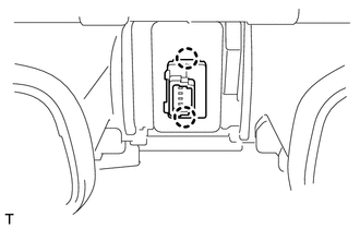
(b) Detach the 2 claws to remove the hazard warning signal switch assembly.
Inspection
INSPECTION
PROCEDURE
1. INSPECT HAZARD WARNING SIGNAL SWITCH ASSEMBLY
|
(a) Measure the resistance according to the value(s) in the table below. Standard Resistance:
|
|
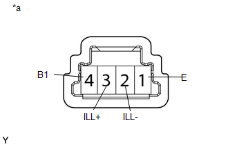
(b) Apply battery voltage to the connector and check the LED illumination condition.
OK:
|
Measurement Condition |
Specified Condition |
|---|---|
|
Battery positive (+) → Terminal 3 (ILL+) Battery negative (-) → Terminal 2 (ILL-) |
LED illuminates |
If the result is not as specified, there may be a malfunction in the hazard warning signal switch.
Text in Illustration|
*a |
Component without harness connected (Hazard Warning Signal Switch Assembly) |
Installation
INSTALLATION
PROCEDURE
1. INSTALL HAZARD WARNING SIGNAL SWITCH ASSEMBLY
(a) Attach the 2 claws to install the hazard warning signal switch assembly.
(b) Connect the connector.
2. INSTALL RADIO AND DISPLAY RECEIVER ASSEMBLY WITH BRACKETS (for Radio and Display Type)
.gif)
3. INSTALL NAVIGATION RECEIVER ASSEMBLY WITH BRACKETS (for Navigation Receiver Type)
4. INSTALL HEATER CONTROL ASSEMBLY
5. INSTALL NO. 1 INSTRUMENT CLUSTER FINISH PANEL GARNISH
6. INSTALL NO. 2 INSTRUMENT CLUSTER FINISH PANEL GARNISH
 Installation
INSTALLATION
CAUTION / NOTICE / HINT
HINT:
Use the same procedure for both the RH and LH sides.
The procedure listed below is for the LH side.
PROCEDURE
1. INSTALL FOG LIGHT ASS ...

Other materials about Toyota 4Runner:
Precaution
PRECAUTION
1. IGNITION SWITCH EXPRESSION
HINT:
The type of ignition switch used on this model differs according to the specifications
of the vehicle. The expressions listed in the table below are used in this section.
Expression
Ign ...
Vehicle Lift And Support Locations
VEHICLE LIFT AND SUPPORT LOCATIONS
1. NOTICE ABOUT VEHICLE CONDITION WHEN RAISING VEHICLE
(a) The vehicle must be unloaded before jacking up or raising the vehicle. Never
jack up or raise a heavily loaded vehicle.
(b) When removing any heavy components li ...

0.0066