Toyota 4Runner: Backup Battery Failure (B15CC)
DESCRIPTION
This DTC is stored when the DCM (Telematics Transceiver) detects one of the following:
- Open or short in the BUB (Back-Up Battery) circuit.
- The BUB (Back-Up Battery) voltage drops or the BUB (Back-Up Battery) malfunctions.
- The BUB (Back-Up Battery) temperature is temporarily high.
|
DTC Code |
DTC Detection Condition |
Trouble Area |
|---|---|---|
|
B15CC |
Back-up battery malfunction. |
|
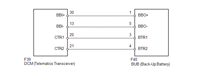
WIRING DIAGRAM
PROCEDURE
|
1. |
CHECK FOR DTC |
(a) Turn the ignition switch off.
(b) Connect the Techstream to the DLC3.
(c) Turn the ignition switch to ON and wait for 10 seconds.
(d) Perform "Health Check" and check for current DTCs (See page
.gif) ).
).
Result
|
Result |
Proceed to |
|---|---|
|
DTC B15CC is output |
A |
|
DTC B15CC is not output |
B |
| B | .gif) |
CHECK FOR INTERMITTENT PROBLEMS |
|
.gif)
|
2. |
CHECK HARNESS AND CONNECTOR (DCM - BUB) |
|
(a) Disconnect the F39 DCM (Telematics Transceiver) connector. |
|
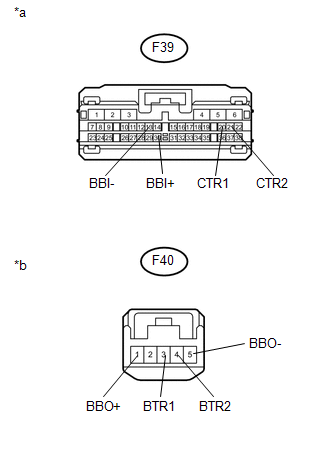
(b) Disconnect the F40 BUB (Back-Up Battery) connector.
(c) Measure the resistance according to the value(s) in the table below.
Standard Resistance:
|
Tester Connection |
Condition |
Specified Condition |
|---|---|---|
|
F39-30 (BBI+) - F40-1 (BBO+) |
Always |
Below 1 Ω |
|
F39-13 (BBI-) - F40-5 (BBO-) |
Always |
Below 1 Ω |
|
F39-20 (CTR1) - F40-3 (BTR1) |
Always |
Below 1 Ω |
|
F39-21 (CTR2) - F40-4 (BTR2) |
Always |
Below 1 Ω |
|
F39-30 (BBI+) - Body ground |
Always |
10 kΩ or higher |
|
F39-13 (BBI-) - Body ground |
Always |
10 kΩ or higher |
|
F39-20 (CTR1) - Body ground |
Always |
10 kΩ or higher |
|
F39-21 (CTR2) - Body ground |
Always |
10 kΩ or higher |
|
*a |
Front view of wire harness connector (to DCM [Telematics Transceiver]) |
|
*b |
Front view of wire harness connector (to BUB [Back-Up Battery]) |
| NG | |
REPAIR OR REPLACE HARNESS OR CONNECTOR |
|
|
3. |
REPLACE BUB (BACK-UP BATTERY) |
(a) Replace the BUB (Back-Up Battery) with a normal one and check that the same
problem does not occur again (See page ).
NOTICE:
The BUB (Back-Up Battery) must not be replaced while an ACN call is in progress
(See page ).
|
|
4. |
CLEAR DTC |
(a) Clear the DTC (See page ).
|
|
5. |
CHECK FOR DTC |
(a) Check for DTCs and check that the same trouble does not occur again (See
page ).
OK:
DTC B15CC is not output.
| OK | |
END |
|
|
6. |
REPLACE DCM (TELEMATICS TRANSCEIVER) |
(a) Replace the DCM (Telematics Transceiver) (See page
).
NOTICE:
- The ignition switch must be off.
- Do not replace the DCM (Telematics Transceiver) with one from another vehicle.
| NEXT | |
PERFORM DCM ACTIVATION |
 Diagnostic Trouble Code Chart
DIAGNOSTIC TROUBLE CODE CHART
HINT:
If a trouble code is stored during the DTC check, inspect the trouble areas listed
for that code. For details of the code, refer to the "See page" bel ...
 Manual Button Malfunction (B15C5)
DESCRIPTION
This DTC is stored when the DCM (Telematics Transceiver) detects an open or short
circuit in the manual (SOS) switch.
DTC Code
DTC Detection Condition
...
Other materials about Toyota 4Runner:
Precaution
PRECAUTION
1. IGNITION SWITCH EXPRESSION
HINT:
The type of ignition switch used on this model differs according to the specifications
of the vehicle. The expressions listed in the table below are used in this section.
Expression
Ign ...
Precaution
PRECAUTION
1. IGNITION SWITCH EXPRESSION
HINT:
The type of ignition switch used on this model differs according to the specifications
of the vehicle. The expressions listed in the table below are used in this section.
Expression
Ign ...

0.0282