Toyota 4Runner: Manual Button Malfunction (B15C5)
DESCRIPTION
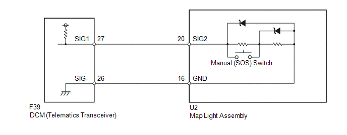
This DTC is stored when the DCM (Telematics Transceiver) detects an open or short circuit in the manual (SOS) switch.
|
DTC Code |
DTC Detection Condition |
Trouble Area |
|---|---|---|
|
B15C5 |
An open or short circuit in the manual (SOS) switch is detected. |
|
WIRING DIAGRAM
PROCEDURE
|
1. |
READ VALUE USING TECHSTREAM (MANUAL [SOS] SWITCH OPERATION) |
(a) Turn the ignition switch off.
(b) Connect the Techstream to the DLC3.
(c) Turn the ignition switch to ON and wait for 10 seconds.
(d) Enter the following menus: Body Electrical / Telematics / Data List.
(e) Check that the manual (SOS) switch condition displayed on the Techstream changes according to the manual (SOS) switch operation.
Telematics|
Tester Display |
Measurement Item/Range |
Normal Condition |
Diagnostic Note |
|---|---|---|---|
|
Emergency Switch |
Manual (SOS) switch / OFF or ON |
OFF: Manual (SOS) switch not pressed |
- |
|
ON: Manual (SOS) switch pressed |
- |
|
Result |
Proceed to |
|---|---|
|
Techstream display changes when turning manual (SOS) switch ON/OFF |
A |
|
Techstream display does not change when turning manual (SOS) switch ON/OFF |
B |
| B | .gif) |
GO TO STEP 3 |
|
.gif)
|
2. |
REPLACE DCM (TELEMATICS TRANSCEIVER) |
(a) Replace the DCM (Telematics Transceiver) (See page
.gif) ).
).
NOTICE:
- The ignition switch must be off.
- Do not replace the DCM (Telematics Transceiver) with one from another vehicle.
| NEXT | |
PERFORM DCM ACTIVATION |
|
3. |
CHECK DCM (TELEMATICS TRANSCEIVER) (SIG1 VOLTAGE) |
|
(a) Remove the DCM (Telematics Transceiver) with the connector connected
(See page |
|
(b) Measure the voltage according to the value(s) in the table below.
Standard Voltage:
|
Tester Connection |
Switch Condition |
Specified Condition |
|---|---|---|
|
F39-27 (SIG1) - F39-26 (SIG-) |
Ignition switch ON, manual (SOS) switch not pressed |
1.5 to 2.0 V |
|
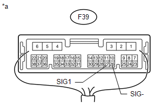
*a |
Component with harness connected (DCM [Telematics Transceiver]) |
| NG | |
GO TO STEP 5 |
|
|
4. |
REPLACE DCM (TELEMATICS TRANSCEIVER) |
(a) Replace the DCM (Telematics Transceiver) (See page
).
NOTICE:
- The ignition switch must be off.
- Do not replace the DCM (Telematics Transceiver) with one from another vehicle.
| NEXT | |
PERFORM DCM ACTIVATION |
|
5. |
INSPECT MAP LIGHT ASSEMBLY (MANUAL [SOS] SWITCH) |
|
(a) Remove the map light assembly (See page
|
|
(b) Measure the resistance according to the value(s) in the table below.
Standard Resistance:
|
Tester Connection |
Switch Condition |
Specified Condition |
|---|---|---|
|
20 (SIG2) - 16 (GND) |
Manual (SOS) switch not pressed |
410 to 414 Ω |
|
20 (SIG2) - 16 (GND) |
Manual (SOS) switch pressed |
81 to 83 Ω |
|
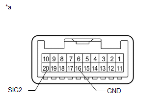
*a |
Component without harness connected (Map Light Assembly) |
| NG | |
REPLACE MAP LIGHT ASSEMBLY |
|
|
6. |
CHECK HARNESS AND CONNECTOR (DCM - MAP LIGHT ASSEMBLY) |
|
(a) Disconnect the F39 DCM (Telematics Transceiver) connector. |
|
(b) Disconnect the U2 map light assembly connector.
(c) Measure the resistance according to the value(s) in the table below.
Standard Resistance:
|
Tester Connection |
Condition |
Specified Condition |
|---|---|---|
|
F39-27 (SIG1) - U2-20 (SIG2) |
Always |
Below 1 Ω |
|
F39-26 (SIG-) - U2-16 (GND) |
Always |
Below 1 Ω |
|
F39-27 (SIG1) - Body ground |
Always |
10 kΩ or higher |
|
F39-26 (SIG-) - Body ground |
Always |
10 kΩ or higher |
|
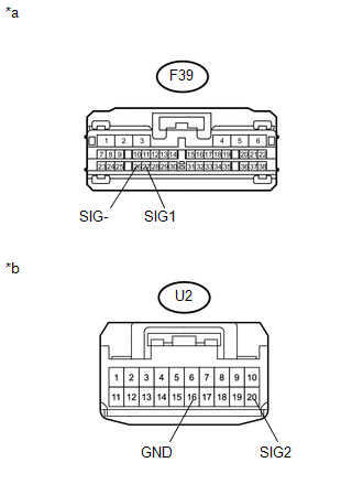
*a |
Front view of wire harness connector (to DCM [Telematics Transceiver]) |
|
*b |
Front view of wire harness connector (to Map Light Assembly) |
| NG | |
REPAIR OR REPLACE HARNESS OR CONNECTOR |
|
|
7. |
REPLACE DCM (TELEMATICS TRANSCEIVER) |
(a) Replace the DCM (Telematics Transceiver) (See page
).
NOTICE:
- The ignition switch must be off.
- Do not replace the DCM (Telematics Transceiver) with one from another vehicle.
| NEXT | |
PERFORM DCM ACTIVATION |
 Backup Battery Failure (B15CC)
DESCRIPTION
This DTC is stored when the DCM (Telematics Transceiver) detects one of the following:
Open or short in the BUB (Back-Up Battery) circuit.
The BUB (Back-Up Battery) voltage dr ...
 Telematics Transceiver Malfunction (B15A8)
DESCRIPTION
This DTC is stored when an error in EEPROM or PLL IC is detected during the DCM
(Telematics Transceiver) self-check. The EEPROM (Electrically Erasable Programmable
Read-Only Memory) s ...
Other materials about Toyota 4Runner:
Sending Malfunction (Navigation to APGS) (U0073,U0140)
DESCRIPTION
These DTCs are stored when a malfunction occurs in the CAN communication circuit.
DTC No.
DTC Detection Condition
Trouble Area
U0073
CAN reception error
CAN communication sys ...
Rear window and outside rear view mirror defoggers
Defoggers are used to defog the rear window, and to remove raindrops, dew
and frost from the outside rear view mirrors.
Before operating the defoggers, make sure the back window is completely
closed.
Vehicles with a manual air conditioning system
Tu ...

0.0071