Toyota 4Runner: Blower Unit
Components
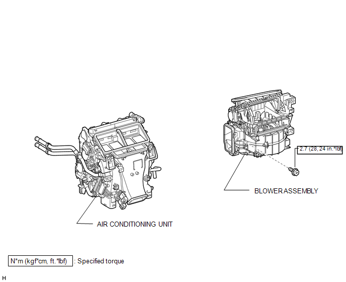
COMPONENTS
ILLUSTRATION
ILLUSTRATION
Removal
REMOVAL
PROCEDURE
1. REMOVE AIR CONDITIONING UNIT
(a) Remove the air conditioning unit (See page
.gif) ).
).
2. REMOVE BLOWER ASSEMBLY
|
(a) Remove the screw. |
|
.png)
(b) Disconnect the connector and detach the clamp.
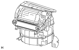
(c) Detach the 2 claws and remove the blower unit.
Disassembly
DISASSEMBLY
PROCEDURE
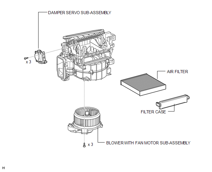
1. REMOVE DAMPER SERVO SUB-ASSEMBLY
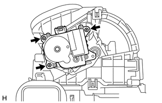
(a) Remove the 3 screws and damper servo sub-assembly.
2. REMOVE BLOWER WITH FAN MOTOR SUB-ASSEMBLY
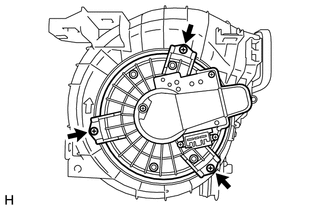
(a) Remove the 3 screws and motor.
3. REMOVE AIR FILTER
(a) Detach the 2 claws and remove the filter.
(b) Remove the filter case.
Reassembly
REASSEMBLY
PROCEDURE
1. INSTALL AIR FILTER
(a) Install the filter.
(b) Attach the 2 claws to install the filter case.
2. INSTALL BLOWER WITH FAN MOTOR SUB-ASSEMBLY
(a) Install the motor with the 3 screws.
3. INSTALL DAMPER SERVO SUB-ASSEMBLY
(a) Install the damper servo with the 3 screws.
Installation
INSTALLATION
PROCEDURE
1. INSTALL BLOWER ASSEMBLY
(a) Attach the 2 claws to install the blower unit.
(b) Connect the connector and attach the clamp.
(c) Install the screw.
Torque:
2.7 N·m {28 kgf·cm, 24 in·lbf}
2. INSTALL AIR CONDITIONING UNIT
(a) Install the air conditioning unit (See page
.gif) ).
).
 Ambient Temperature Sensor
Components
COMPONENTS
ILLUSTRATION
Inspection
INSPECTION
PROCEDURE
1. INSPECT COOLER THERMISTOR (AMBIENT TEMPERATURE SENSOR)
(a) Measure the resistance according to the value(s) in th ...
 Compressor
...
Other materials about Toyota 4Runner:
Operation Check
OPERATION CHECK
1. INSPECT DRIVER SIDE SEAT BELT WARNING LIGHT
(a) Turn the ignition switch to ON.
(b) When the driver seat belt is not fastened, check that the seat belt warning
light on the combination meter assembly blinks for 6 seconds. After 1.8 seco ...
Precaution
PRECAUTION
1. TIRE PRESSURE WARNING ECU EXPRESSIONS
(a) The tire pressure monitor receiver assembly is referred to as the tire pressure
warning ECU in this section.
2. TIRE PRESSURE WARNING SYSTEM PRECAUTION
(a) It is necessary for the tire pressures to ...

0.0065