Toyota 4Runner: Ambient Temperature Sensor
Components
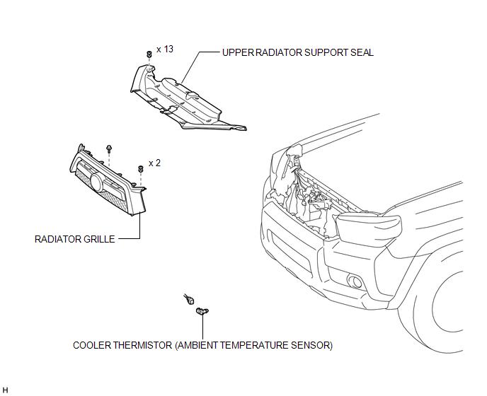
COMPONENTS
ILLUSTRATION
Inspection
INSPECTION
PROCEDURE
1. INSPECT COOLER THERMISTOR (AMBIENT TEMPERATURE SENSOR)
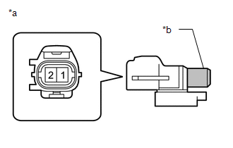
(a) Measure the resistance according to the value(s) in the table below.
Standard Resistance:
|
Tester Connection |
Condition |
Specified Condition |
|---|---|---|
|
1 - 2 |
10°C (50°F) |
3.00 to 3.73 kΩ |
|
15°C (59°F) |
2.45 to 2.88 kΩ |
|
|
20°C (68°F) |
1.95 to 2.30 kΩ |
|
|
25°C (77°F) |
1.60 to 1.80 kΩ |
|
|
30°C (86°F) |
1.28 to 1.47 kΩ |
|
|
35°C (95°F) |
1.00 to 1.22 kΩ |
|
|
40°C (104°F) |
0.80 to 1.00 kΩ |
|
|
45°C (113°F) |
0.65 to 0.85 kΩ |
|
|
50°C (122°F) |
0.50 to 0.70 kΩ |
|
|
55°C (131°F) |
0.44 to 0.60 kΩ |
|
|
60°C (140°F) |
0.36 to 0.50 kΩ |
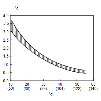
HINT:
As the temperature increases, the resistance decreases (refer to the graph).
NOTICE:
- Touching the sensor even slightly may change the resistance value. Hold the connector of the sensor.
- When measuring the resistance, make sure the sensor temperature is the same as the ambient temperature.
If the result is not as specified, replace the cooler thermistor (ambient temperature sensor).
Text in Illustration|
*a |
Component without harness connected (Ambient Temperature Sensor) |
|
*b |
Sensor Area |
|
*c |
Resistance (kΩ) |
|
*d |
Temperature (°C(°F)) |
Installation
INSTALLATION
PROCEDURE
1. INSTALL COOLER THERMISTOR (AMBIENT TEMPERATURE SENSOR)
(a) Attach the clamp to install the sensor.
(b) Connect the connector.
2. INSTALL RADIATOR GRILLE
(a) Install the radiator grille (See page .gif) ).
).
3. INSTALL UPPER RADIATOR SUPPORT SEAL
Removal
REMOVAL
PROCEDURE
1. REMOVE UPPER RADIATOR SUPPORT SEAL
.gif)
2. REMOVE RADIATOR GRILLE
(a) Remove the radiator grille (See page ).
3. REMOVE COOLER THERMISTOR (AMBIENT TEMPERATURE SENSOR)
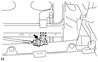
(a) Disconnect the connector.
(b) Using a screwdriver, detach the clamp and remove the sensor.
HINT:
Tape the screwdriver tip before use.
 Reassembly
REASSEMBLY
PROCEDURE
1. INSTALL NO. 1 COOLER THERMISTOR
NOTICE:
If reusing the evaporator, do not insert the thermistor into a location where
the thermistor was previously inserted.
(a) Inser ...
 Blower Unit
Components
COMPONENTS
ILLUSTRATION
ILLUSTRATION
Removal
REMOVAL
PROCEDURE
1. REMOVE AIR CONDITIONING UNIT
(a) Remove the air conditioning unit (See page
).
2. REMOVE BLOWER ASSEMBLY ...
Other materials about Toyota 4Runner:
Screen Flicker or Color Distortion
PROCEDURE
1.
CHECK DISPLAY SETTING
(a) Reset display settings (contrast, brightness) and check that the screen appears
normal.
OK:
The display returns to normal.
OK
END
NG
...
Initialization
INITIALIZATION
1. INITIALIZE SLIDING ROOF DRIVE GEAR SUB-ASSEMBLY
NOTICE:
Before starting this operation, make sure that the guide rails are not
deformed and there is no foreign object on the guide rails.
When the sliding roof glass is adjus ...

0.0084