Toyota 4Runner: Center Differential Lock Position Switch (C1282)
DESCRIPTION
DTC C1282 is stored only in test mode.
|
DTC Code |
DTC Detection Condition |
Trouble Area |
|---|---|---|
|
C1282 |
Stored during test mode. |
|
HINT:
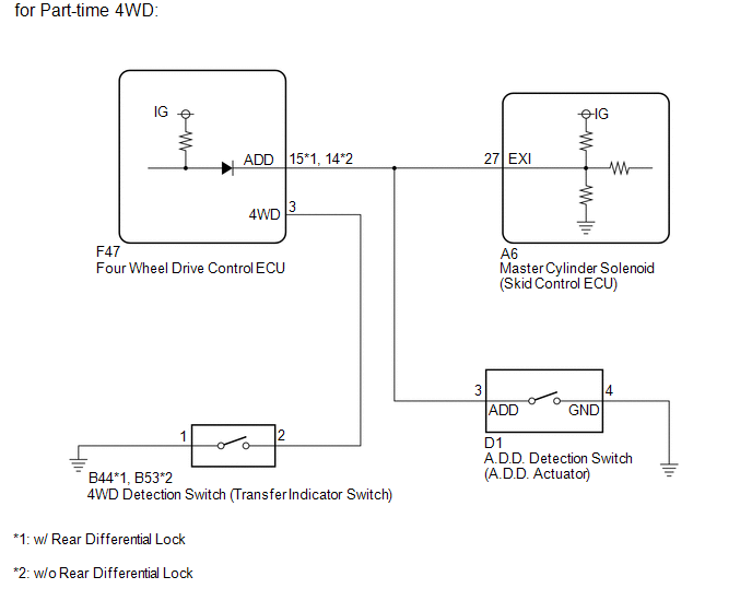
- For vehicles with part-time 4WD, this DTC indicates problems when shifting from 2WD to 4WD.
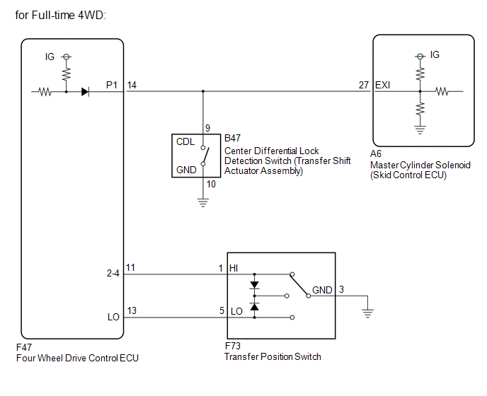
- For vehicles with full-time 4WD, this DTC indicates problems when switching the state of the center differential lock.
WIRING DIAGRAM
CAUTION / NOTICE / HINT
NOTICE:
When replacing the master cylinder solenoid, perform calibration (See page
.gif) ).
).
PROCEDURE
|
1. |
CONFIRM VEHICLE SPECIFICATIONS |
(a) Confirm the vehicle specifications.
Result|
Result |
Proceed to |
|---|---|
|
for Part-time 4WD |
A |
|
for Full-time 4WD |
B |
| B | .gif) |
GO TO STEP 5 |
|
.gif)
|
2. |
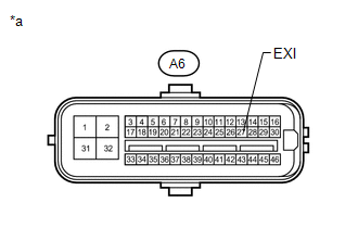
CHECK TERMINAL VOLTAGE (EXI) |
(a) Disconnect the A6 skid control ECU connector.
|
(b) Measure the voltage according to the value(s) in the table below. Standard Voltage:
|
|
| NG | |
GO TO STEP 4 |
|
|
3. |
CHECK TEST MODE DTC |
(a) Switch the vehicle to test mode, perform the 4WD detection switch signal
check, and then check that DTC C1282 is cleared (See page
).
Result
|
Result |
Proceed to |
|---|---|
|
DTC is not cleared |
A |
|
DTC is cleared |
B |
| A | |
REPLACE MASTER CYLINDER SOLENOID |
| B | |
USE SIMULATION METHOD TO CHECK |
|
4. |
CHECK HARNESS AND CONNECTOR (SKID CONTROL ECU - FOUR WHEEL DRIVE CONTROL ECU AND A.D.D. ACTUATOR) |
(a) Disconnect the A6 skid control ECU connector.
(b) Disconnect the F47 four wheel drive control ECU connector.
(c) Disconnect the D1 A.D.D. actuator connector.
(d) Measure the resistance according to the value(s) in the table below.
Standard Resistance:
w/ Rear Differential Lock|
Tester Connection |
Condition |
Specified Condition |
|---|---|---|
|
A6-27 (EXI) - F47-15 (ADD) |
Always |
Below 1 Ω |
|
A6-27 (EXI) - D1-3 (ADD) |
Always |
Below 1 Ω |
|
A6-27 (EXI) - Body ground |
Always |
10 kΩ or higher |
:
w/o Rear Differential Lock|
Tester Connection |
Condition |
Specified Condition |
|---|---|---|
|
A6-27 (EXI) - F47-14 (ADD) |
Always |
Below 1 Ω |
|
A6-27 (EXI) - D1-3 (ADD) |
Always |
Below 1 Ω |
|
A6-27 (EXI) - Body ground |
Always |
10 kΩ or higher |
| OK | |
GO TO TRANSFER SYSTEM (PROBLEM SYMPTOMS TABLE) |
| NG | |
REPAIR OR REPLACE HARNESS OR CONNECTOR |
|
5. |
CHECK TERMINAL VOLTAGE (EXI) |
(a) Disconnect the A6 skid control ECU connector.
|
(b) Measure the voltage according to the value(s) in the table below. Standard Voltage:
|
|
| NG | |
GO TO STEP 7 |
|
|
6. |
CHECK TEST MODE DTC |
(a) Switch the vehicle to test mode, perform the center differential lock detection
signal check, and then check that DTC C1282 is cleared (See page
).
Result
|
Result |
Proceed to |
|---|---|
|
DTC is not cleared |
A |
|
DTC is cleared |
B |
| A | |
REPLACE MASTER CYLINDER SOLENOID |
| B | |
USE SIMULATION METHOD TO CHECK |
|
7. |
CHECK HARNESS AND CONNECTOR (SKID CONTROL ECU - FOUR WHEEL DRIVE CONTROL ECU AND TRANSFER SHIFT ACTUATOR ASSEMBLY) |
(a) Disconnect the A6 skid control ECU connector.
(b) Disconnect the F47 four wheel drive control ECU connector.
(c) Disconnect the B47 transfer shift actuator assembly connector.
(d) Measure the resistance according to the value(s) in the table below.
Standard Resistance:
|
Tester Connection |
Condition |
Specified Condition |
|---|---|---|
|
A6-27 (EXI) - F47-14 (P1) |
Always |
Below 1 Ω |
|
A6-27 (EXI) - B47-9 (CDL) |
Always |
Below 1 Ω |
|
A6-27 (EXI) - Body ground |
Always |
10 kΩ or higher |
| OK | |
GO TO TRANSFER SYSTEM (PROBLEM SYMPTOMS TABLE) |
| NG | |
REPAIR OR REPLACE HARNESS OR CONNECTOR |
 Transfer L4 Position Switch Circuit (C1268)
DESCRIPTION
DTC Code
DTC Detection Condition
Trouble Area
C1268
The skid control ECU receives an L4 abnormal status signal from the four
...
 Steering Angle Sensor Zero Point Malfunction (C1290)
DESCRIPTION
The skid control ECU acquires steering angle sensor zero point every time the
ignition switch is turned to ON and the vehicle is driven at 40 km/h (25 mph) or
more for approximately 1 ...
Other materials about Toyota 4Runner:
Inspection
INSPECTION
PROCEDURE
1. INSPECT NO. 1 SPEAKER ASSEMBLY WITH BOX
(a) Measure the resistance according to the value(s) in the table below.
Standard Resistance:
Tester Connection
Condition
Sp ...
Removal
REMOVAL
CAUTION / NOTICE / HINT
HINT:
Use the same procedure for the RH and LH sides.
The procedure listed below is for the LH side.
PROCEDURE
1. REMOVE REAR NO. 1 FLOOR STEP COVER (w/ Rear No. 2 Seat)
2. REMOVE QUARTER SCUFF PLATE L ...

0.0091