Toyota 4Runner: Certification ECU Communication Stop Mode
DESCRIPTION
|
Detection Item |
Symptoms |
Trouble Area |
|---|---|---|
|
Certification ECU Communication Stop Mode |
Either condition is met:
|
|
HINT:
For vehicles with a smart key system only.
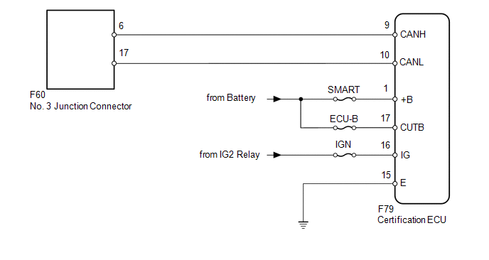
WIRING DIAGRAM
CAUTION / NOTICE / HINT
NOTICE:
Inspect the fuses for circuits related to this system before performing the following inspection procedure.
HINT:
Operating the ignition switch, any switches or any doors triggers related ECU and sensor communication with the CAN, which causes resistance variation.
PROCEDURE
|
1. |
DISCONNECT CABLE FROM NEGATIVE BATTERY TERMINAL |
(a) Disconnect the cable from the negative (-) battery terminal before measuring the resistances of the main wire or branch wire.
CAUTION:
Wait at least 90 seconds after disconnecting the cable from the negative (-) battery terminal to disable the SRS system.
NOTICE:
When disconnecting the cable, some systems need to be initialized after the cable
is reconnected (See page .gif) ).
).
|
.gif)
|
2. |
CHECK FOR OPEN IN CAN BUS WIRE (CERTIFICATION ECU BRANCH WIRE) |
|
(a) Disconnect the F79 certification ECU connector. |
|
(b) Measure the resistance according to the value(s) in the table below.
Standard Resistance:
|
Tester Connection |
Switch Condition |
Specified Condition |
|---|---|---|
|
F79-9 (CANH) - F79-10 (CANL) |
Ignition switch off |
54 to 69 Ω |
|
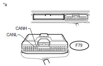
*a |
Rear view of wire harness connector (to Certification ECU) |
| NG | .gif) |
REPAIR OR REPLACE CERTIFICATION ECU BRANCH WIRE OR CONNECTOR (CANH, CANL) |
|
|
3. |
CHECK HARNESS AND CONNECTOR (CERTIFICATION ECU - BATTERY AND BODY GROUND) |
|
(a) Connect the cable to the negative (-) battery terminal. NOTICE: When disconnecting the cable, some systems need to be initialized after
the cable is reconnected (See page |
|
(b) Measure the resistance according to the value(s) in the table below.
Standard Resistance:
|
Tester Connection |
Condition |
Specified Condition |
|---|---|---|
|
F79-15 (E) - Body ground |
Always |
Below 1 Ω |
(c) Measure the voltage according to the value(s) in the table below.
Standard Voltage:
|
Tester Connection |
Switch Condition |
Specified Condition |
|---|---|---|
|
F79-1 (+B) - Body ground |
Always |
11 to 14 V |
|
F79-16 (IG) - Body ground |
Ignition switch ON |
11 to 14 V |
|
F79-17 (CUTB) - Body ground |
Always |
11 to 14 V |
|
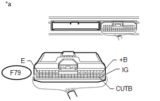
*a |
Rear view of wire harness connector (to Certification ECU) |
| OK | |
REPLACE CERTIFICATION ECU |
| NG | |
REPAIR OR REPLACE HARNESS OR CONNECTOR |
 Combination Meter ECU Communication Stop Mode
DESCRIPTION
Detection Item
Symptom
Trouble Area
Combination Meter ECU Communication Stop Mode
Either condition is met:
" ...
 Center Airbag Sensor Communication Stop Mode
DESCRIPTION
Detection Item
Symptom
Trouble Area
Center Airbag Sensor Communication Stop Mode
Either condition is met:
" ...
Other materials about Toyota 4Runner:
Speed Sensor Circuit Malfunction (C1883/83)
DESCRIPTION
The stabilizer control ECU receives the speed signal from the skid control ECU
via CAN communication.
DTC Code
DTC Detection Condition
Trouble Area
C1883/83
The stabilizer control ECU ...
Reassembly
REASSEMBLY
PROCEDURE
1. ASSEMBLE DIFFERENTIAL CASE
(a) Install the rear differential side gear thrust washer to the rear differential
side gear.
(b) Install the rear differential pinion thrust washer and rear differential
pinion to the rear different ...

0.0258