Toyota 4Runner: Center Airbag Sensor Communication Stop Mode
DESCRIPTION
|
Detection Item |
Symptom |
Trouble Area |
|---|---|---|
|
Center Airbag Sensor Communication Stop Mode |
Either condition is met:
|
|
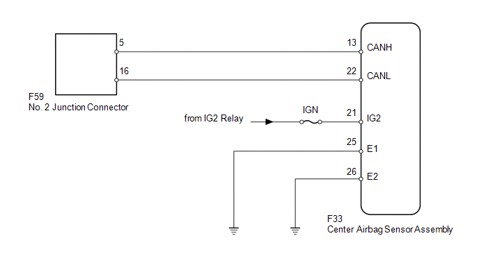
WIRING DIAGRAM
CAUTION / NOTICE / HINT
NOTICE:
Inspect the fuses for circuits related to this system before performing the following inspection procedure.
HINT:
Operating the ignition switch, any switches or any doors triggers related ECU and sensor communication with the CAN, which causes resistance variation.
PROCEDURE
|
1. |
DISCONNECT CABLE FROM NEGATIVE BATTERY TERMINAL |
(a) Disconnect the cable from the negative (-) battery terminal before measuring the resistances of the main wire and branch wire.
CAUTION:
Wait at least 90 seconds after disconnecting the cable from the negative (-) battery terminal to disable the SRS system.
NOTICE:
When disconnecting the cable, some systems need to be initialized after the cable
is reconnected (See page .gif) ).
).
|
.gif)
|
2. |
CHECK FOR OPEN IN CAN BUS WIRE (CENTER AIRBAG SENSOR ASSEMBLY BRANCH WIRE) |
|
(a) Disconnect the F33 center airbag sensor assembly connector. |
|
(b) Measure the resistance according to the value(s) in the table below.
Standard Resistance:
|
Tester Connection |
Switch Condition |
Specified Condition |
|---|---|---|
|
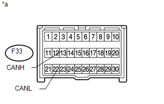
F33-13 (CANH) - F33-22 (CANL) |
Ignition switch off |
54 to 69 Ω |
|
*a |
Front view of wire harness connector (to Center Airbag Sensor Assembly) |
| NG | .gif) |
REPAIR OR REPLACE CENTER AIRBAG SENSOR ASSEMBLY BRANCH WIRE OR CONNECTOR (CANH, CANL) |
|
|
3. |
CHECK HARNESS AND CONNECTOR (CENTER AIRBAG SENSOR ASSEMBLY - BATTERY AND BODY GROUND) |
|
(a) Connect the cable to the negative (-) battery terminal. NOTICE: When disconnecting the cable, some systems need to be initialized after
the cable is reconnected (See page |
|
(b) Measure the resistance according to the value(s) in the table below.
Standard Resistance:
|
Tester Connection |
Condition |
Specified Condition |
|---|---|---|
|
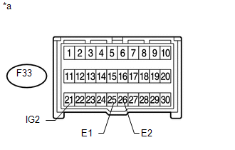
F33-25 (E1) - Body ground |
Always |
Below 1 Ω |
|
F33-26 (E2) - Body ground |
(c) Measure the voltage according to the value(s) in the table below.
Standard Voltage:
|
Tester Connection |
Switch Condition |
Specified Condition |
|---|---|---|
|
F33-21 (IG2) - Body ground |
Ignition switch ON |
11 to 14 V |
|
*a |
Front view of wire harness connector (to Center Airbag Sensor Assembly) |
| OK | |
REPLACE CENTER AIRBAG SENSOR ASSEMBLY |
| NG | |
REPAIR OR REPLACE HARNESS OR CONNECTOR |
 Certification ECU Communication Stop Mode
DESCRIPTION
Detection Item
Symptoms
Trouble Area
Certification ECU Communication Stop Mode
Either condition is met:
"Ce ...
 4WD Control ECU Communication Stop Mode
DESCRIPTION
Detection Item
Symptom
Trouble Area
4WD Control ECU Communication Stop Mode
Either condition is met:
"Four ...
Other materials about Toyota 4Runner:
On-vehicle Inspection
ON-VEHICLE INSPECTION
PROCEDURE
1. INSPECT HOOD SUB-ASSEMBLY
(a) Check that the clearance measurements of areas A through E are within each
standard range.
Standard:
Area
Measurement
Area
Measurement
...
Inspection
INSPECTION
PROCEDURE
1. INSPECT REAR NO. 1 SEAT OUTER BELT ASSEMBLY
(a) Check the ELR.
(1) When the inclination of the retractor is 15° or less, check that
the belt can be pulled from the retractor. When the inclination of the retractor
...

0.0261