Toyota 4Runner: Combination Meter
Components
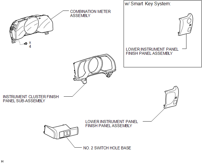
COMPONENTS
ILLUSTRATION
ILLUSTRATION
ILLUSTRATION
Removal
REMOVAL
PROCEDURE
1. DISCONNECT CABLE FROM NEGATIVE BATTERY TERMINAL
CAUTION:
Wait at least 90 seconds after disconnecting the cable from the negative (-) battery terminal to disable the SRS system.
NOTICE:
When disconnecting the cable, some systems need to be initialized after the cable
is reconnected (See page .gif) ).
).
2. REMOVE NO. 2 SWITCH HOLE BASE
3. REMOVE LOWER INSTRUMENT PANEL FINISH PANEL ASSEMBLY
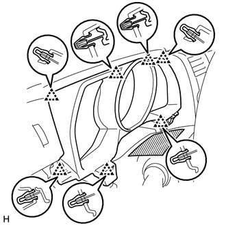
4. REMOVE INSTRUMENT CLUSTER FINISH PANEL SUB-ASSEMBLY
(a) Operate the tilt and telescopic lever to fully extend and lower the steering column assembly.
|
(b) Place protective tape as shown in the illustration. Text in Illustration
|
|
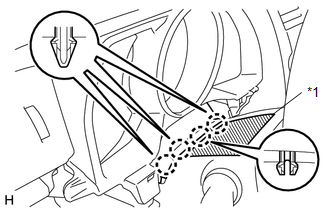
(c) Detach the 4 claws.
|
(d) Detach the 7 clips and remove the finish panel. |
|
5. REMOVE COMBINATION METER ASSEMBLY
|
(a) Remove the 4 screws. |
|
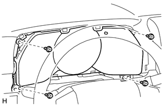
(b) Disconnect the connectors and remove the combination meter by pulling it up in the direction of the arrow in the illustration.
Disassembly
DISASSEMBLY
PROCEDURE
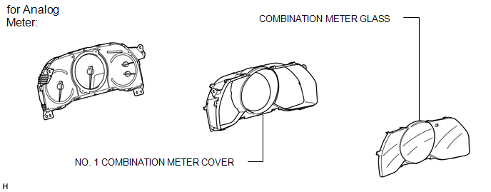
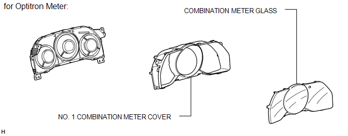
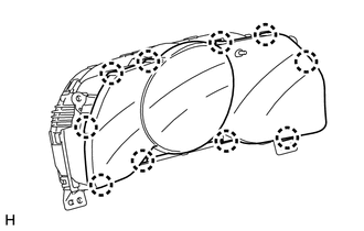
1. REMOVE COMBINATION METER GLASS
|
(a) Detach the 10 claws and remove the meter glass. |
|
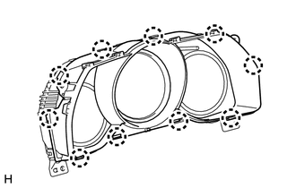
2. REMOVE NO. 1 COMBINATION METER COVER
|
(a) Detach the 10 claws and remove the cover. |
|
Reassembly
REASSEMBLY
PROCEDURE
1. INSTALL NO. 1 COMBINATION METER COVER
(a) Attach the 10 claws to install the cover.
2. INSTALL COMBINATION METER GLASS
(a) Attach the 10 claws to install the meter glass.
Installation
INSTALLATION
PROCEDURE
1. INSTALL COMBINATION METER ASSEMBLY
(a) Connect the connectors.
(b) Install the combination meter with the 4 screws.
2. INSTALL INSTRUMENT CLUSTER FINISH PANEL SUB-ASSEMBLY
(a) Attach the 7 claws to install the finish panel.
(b) Attach the 4 claws.
3. INSTALL LOWER INSTRUMENT PANEL FINISH PANEL ASSEMBLY
.gif)
4. INSTALL NO. 2 SWITCH HOLE BASE
5. CONNECT CABLE TO NEGATIVE BATTERY TERMINAL
NOTICE:
When disconnecting the cable, some systems need to be initialized after the cable
is reconnected (See page ).
 Terminals Of Ecu
TERMINALS OF ECU
1. ACCESSORY METER ASSEMBLY
(a) Measure the voltage and resistance according to the value(s) in the table
below.
Terminal No. (Symbol)
Wiring Color
...
 Light Control Rheostat
Components
COMPONENTS
ILLUSTRATION
Inspection
INSPECTION
PROCEDURE
1. INSPECT LIGHT CONTROL RHEOSTAT (w/o TAIL Cancel Switch)
(a) Measure the resistance according to the value(s) in the t ...
Other materials about Toyota 4Runner:
How To Proceed With Troubleshooting
CAUTION / NOTICE / HINT
HINT:
Use the following procedure to troubleshoot the wiper and washer system.
*: Use the Techstream.
PROCEDURE
1.
VEHICLE BROUGHT TO WORKSHOP
NEXT
...
Rear Occupant Classification Sensor RH Collision Detection (B1788)
DESCRIPTION
DTC B1788 is stored when the occupant classification ECU receives a collision
detection signal, which is sent by the occupant classification sensor rear RH when
an accident occurs.
DTC B1788 is also stored when the separate type front seat cu ...

0.0254