Toyota 4Runner: Light Control Rheostat
Components
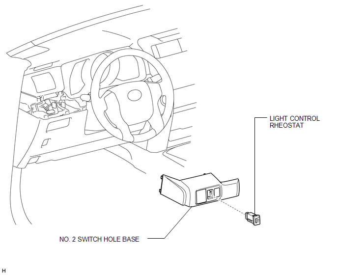
COMPONENTS
ILLUSTRATION
Inspection
INSPECTION
PROCEDURE
1. INSPECT LIGHT CONTROL RHEOSTAT (w/o TAIL Cancel Switch)
(a) Measure the resistance according to the value(s) in the table below.
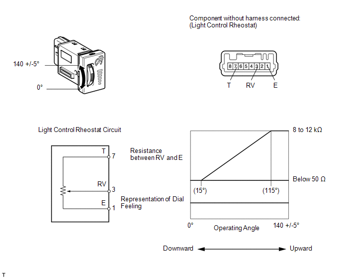
Standard Resistance:
|
Tester Connection |
Switch Condition |
Specified Condition |
|---|---|---|
|
7 (T) - 1 (E) |
Always |
8 to 12 kΩ |
|
3 (RV) - 1 (E) |
Light control rheostat fully turned upward → fully turned downward |
8 to 12 kΩ → Below 50 Ω |
If the result is not as specified, replace the rheostat.
2. INSPECT LIGHT CONTROL RHEOSTAT (w/ TAIL Cancel Switch)
(a) Measure the resistance according to the value(s) in the table below.
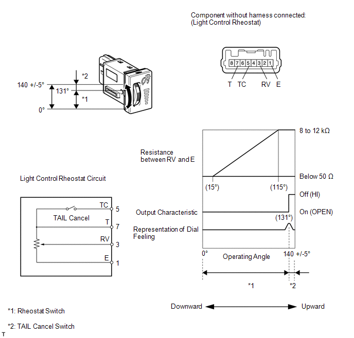
Standard Resistance:
|
Tester Connection |
Switch Condition |
Specified Condition |
|---|---|---|
|
7 (T) - 1 (E) |
Always |
8 to 12 kΩ |
|
5 (TC) - 7 (T) |
TAIL cancel switch off → on |
Below 50 Ω → 8 to 12 kΩ |
|
3 (RV) - 1 (E) |
Light control rheostat fully turned upward → fully turned downward |
8 to 12 kΩ → Below 50 Ω |
If the result is not as specified, replace the rheostat.
Installation
INSTALLATION
PROCEDURE
1. INSTALL LIGHT CONTROL RHEOSTAT
(a) Attach the 2 claws to install the rheostat.
2. INSTALL NO. 2 SWITCH HOLE BASE
.gif)
Removal
REMOVAL
PROCEDURE
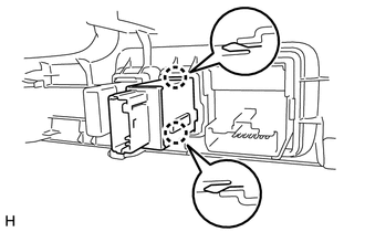
1. REMOVE NO. 2 SWITCH HOLE BASE
.gif)
2. REMOVE LIGHT CONTROL RHEOSTAT
|
(a) Detach the 2 claws and remove the rheostat. |
|
 Combination Meter
Components
COMPONENTS
ILLUSTRATION
ILLUSTRATION
ILLUSTRATION
Removal
REMOVAL
PROCEDURE
1. DISCONNECT CABLE FROM NEGATIVE BATTERY TERMINAL
CAUTION:
Wait at least 90 seconds after di ...

Other materials about Toyota 4Runner:
Reassembly
REASSEMBLY
PROCEDURE
1. INSTALL LOWER BALL JOINT DUST COVER LH
(a) Pack the lower arm ball joint with MP grease.
Grease capacity:
8.0 g (0.282 oz.)
(b) Apply MP grease to the locations shown in the illustration.
Text in Illustration
...
Short to Battery in Motor RH Circuit (25,26)
DESCRIPTION
When there is a short to battery in the side auto step motor circuit, the side
auto step controller ECU assembly will not operate the automatic running board.
DTC No.
Detection Condition
Trouble Area
...

0.0116