Toyota 4Runner: Components
COMPONENTS
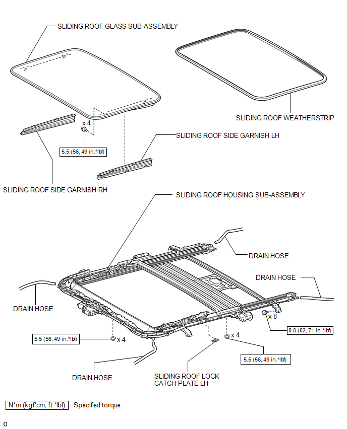
ILLUSTRATION
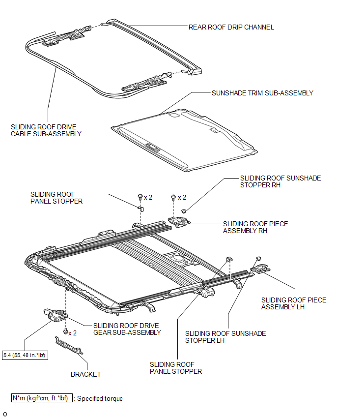
ILLUSTRATION

 Removal
REMOVAL
PROCEDURE
1. DISCONNECT CABLE FROM NEGATIVE BATTERY TERMINAL
CAUTION:
Wait at least 90 seconds after disconnecting the cable from the negative (-)
battery terminal to disable the SRS sys ...
Other materials about Toyota 4Runner:
Transmission Control Cable
Components
COMPONENTS
ILLUSTRATION
Removal
REMOVAL
PROCEDURE
1. REMOVE CONSOLE BOX ASSEMBLY
(a) Remove the console box assembly (See page
).
2. REMOVE TRANSMISSION CONTROL CABLE ASSEMBLY
(a) Move the shift lever to N.
(b) Disconne ...
Scanning radio stations (excluding XM® Satellite Radio)
Scanning the preset radio stations
Press and hold
until you hear a beep.
Preset stations will be played for 5 seconds each.
When the desired station is
reached, press again.
Scanning all radio stations within range
Press
.
All the stations wit ...
© 2016-2026 | www.to4runner.net

0.0067
0.0067