Toyota 4Runner: Removal
REMOVAL
PROCEDURE
1. DISCONNECT CABLE FROM NEGATIVE BATTERY TERMINAL
CAUTION:
Wait at least 90 seconds after disconnecting the cable from the negative (-) battery terminal to disable the SRS system.
NOTICE:
When disconnecting the cable, some systems need to be initialized after the cable
is reconnected (See page .gif) ).
).
2. REMOVE ROOF HEADLINING ASSEMBLY
(a) Remove the roof headlining assembly (See page
).
3. REMOVE CURTAIN SHIELD AIRBAG ASSEMBLY LH
(a) Remove the curtain shield airbag assembly LH (See page
).
4. REMOVE CURTAIN SHIELD AIRBAG ASSEMBLY RH
HINT:
Use the same procedures described for the LH side.
5. REMOVE SLIDING ROOF SIDE GARNISH LH
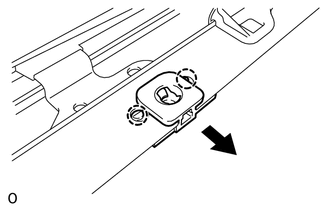
(a) Detach the 5 claws and remove the side garnish.
6. REMOVE SLIDING ROOF SIDE GARNISH RH
HINT:
Use the same procedures described for the LH side.
7. REMOVE SLIDING ROOF GLASS SUB-ASSEMBLY
(a) Using a T25 "TORX" driver, remove the 4 screws and glass.
8. REMOVE SLIDING ROOF WEATHERSTRIP
(a) Remove the sliding roof weatherstrip.
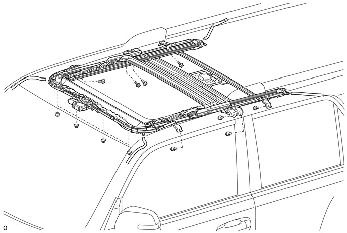
9. REMOVE SLIDING ROOF HOUSING SUB-ASSEMBLY
(a) Disconnect the 4 sliding roof drain hoses.
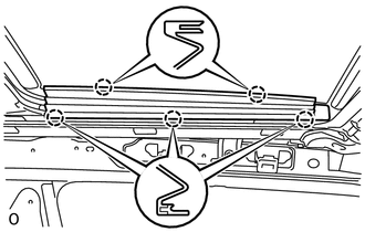
(b) Remove the 8 bolts and 4 nuts.
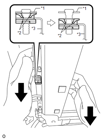
(c) Loosen the 4 nuts as shown in the illustration.
NOTICE:
Be sure that the nuts are fully threaded onto the bolts.
|
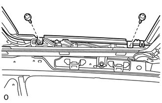
(d) Pull the sliding roof housing sub-assembly downward and detach the 2 claws of the sliding roof lock catch plate LH from the stud bolt as shown in the illustration. Text in Illustration
NOTICE: Performing this procedure breaks the claws of the sliding roof lock catch plate LH so that the sliding roof housing sub-assembly can be removed. However, do not use excessive force. |
|
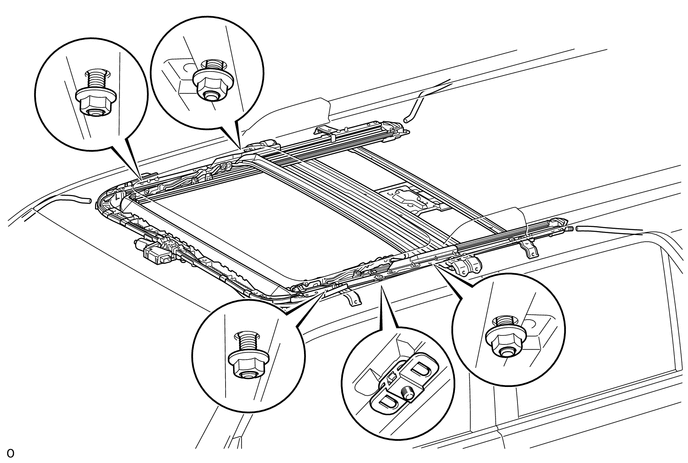
(e) Remove the 4 nuts and sliding roof housing sub-assembly.
|
(f) Detach the 2 claws and remove the sliding roof lock catch plate LH from the sliding roof housing sub-assembly. HINT: The sliding roof lock catch plate LH is used when the vehicle is assembled at the factory and is not needed for reinstallation. |
|
 Components
COMPONENTS
ILLUSTRATION
ILLUSTRATION
...
 Disassembly
DISASSEMBLY
PROCEDURE
1. REMOVE SLIDING ROOF DRIVE GEAR SUB-ASSEMBLY
(a) Detach the bracket claw and remove the bracket.
(b) Remove the 2 bolts ...
Other materials about Toyota 4Runner:
Glossary Of Sae And Toyota Terms
GLOSSARY OF SAE AND TOYOTA TERMS
This glossary lists all SAE-J1930 terms and abbreviations used in this manual
in compliance with SAE recommendations, as well as their TOYOTA equivalents.
SAE
Abbreviation
SAE Term
TOYOTA ...
Data List / Active Test
DATA LIST / ACTIVE TEST
1. READ DATA LIST
HINT:
Using the Techstream to read the Data List allows the values or states of switches,
sensors, actuators and other items to be read without removing any parts. This non-intrusive
inspection can be very usefu ...

0.0274