Toyota 4Runner: Compressor Lock Sensor Circuit (B1422)
SYSTEM DESCRIPTION
The ECM sends the engine speed signal to the air conditioning amplifier assembly via CAN communication.
The air conditioning amplifier assembly reads the difference between compressor speed and engine speed. When the difference becomes too large, the air conditioning amplifier assembly determines that the cooler compressor assembly is locked and turns the magnet clutch assembly off.
|
DTC Code |
DTC Detection Condition |
Trouble Area |
|---|---|---|
|
B1422 |
Open or short in the compressor lock sensor circuit. |
|
WIRING DIAGRAM

CAUTION / NOTICE / HINT
HINT:
As DTC B1422 is also output when the compressor drive belt is damaged or loose, inspect the belt before performing troubleshooting.
PROCEDURE
|
1. |
CHECK FOR DTC (CAN COMMUNICATION SYSTEM) |
(a) Use the Techstream to check if the CAN communication system is functioning normally.
Result|
Result |
Proceed to |
|---|---|
|
CAN DTC is not output |
A |
|
CAN DTC is output |
B |
| B | .gif) |
GO TO CAN COMMUNICATION SYSTEM |
|
.gif)
|
2. |
INSPECT COOLER COMPRESSOR ASSEMBLY (A/C LOCK SENSOR) |
|
(a) Remove the cooler compressor assembly (A/C lock sensor) (See page
|
|
.gif) ).
).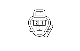
(b) Measure the resistance according to the value(s) in the table below.
Standard Resistance:
|
Tester Connection |
Condition |
Specified Condition |
|---|---|---|
|
1 - 2 |
20°C (68°F) |
160 to 320 Ω |
| NG | |
REPLACE COOLER COMPRESSOR ASSEMBLY (A/C LOCK SENSOR) |
|
|
3. |
CHECK HARNESS AND CONNECTOR (AIR CONDITIONING AMPLIFIER - A/C LOCK SENSOR) |
(a) Disconnect the F42 amplifier connector.
(b) Disconnect the B41 sensor connector.
(c) Measure the resistance according to the value(s) in the table below.
Standard Resistance:
|
Tester Connection |
Condition |
Specified Condition |
|---|---|---|
|
F42-8 (LOCK) - B41-1 |
Always |
Below 1 Ω |
|
F42-13 (SG-2) - B41-2 |
Always |
Below 1 Ω |
|
F42-8 (LOCK) - Body ground |
Always |
10 kΩ or higher |
|
F42-13 (SG-2) - Body ground |
Always |
10 kΩ or higher |
|
Result |
Proceed to |
|---|---|
|
OK (When troubleshooting according to problem symptoms table) |
A |
|
OK (When troubleshooting according to the DTC) |
B |
|
NG |
C |
| A | |
PROCEED TO NEXT SUSPECTED AREA SHOWN IN PROBLEM SYMPTOMS TABLE |
| B | |
REPLACE AIR CONDITIONING AMPLIFIER ASSEMBLY |
| C | |
REPAIR OR REPLACE HARNESS OR CONNECTOR |
 Diagnostic Trouble Code Chart
DIAGNOSTIC TROUBLE CODE CHART
HINT:
If a trouble code is output during the DTC check, inspect the trouble
areas listed for that code. For details of the code, refer to the "See page ...
 Lost Communication with ECM (U0100,U0142,U0155)
DESCRIPTION
The air conditioning amplifier communicates with the ECM, main body ECU (multiplex
network body ECU) and combination meter through the CAN communication system.
DTC Code
...
Other materials about Toyota 4Runner:
Installation
INSTALLATION
CAUTION / NOTICE / HINT
HINT:
Use the same procedure for the RH and LH sides.
The procedure listed below is for the LH side.
When installing the window frame moulding, heat the vehicle body and
window frame moulding using a ...
Solar Sensor
Components
COMPONENTS
ILLUSTRATION
Inspection
INSPECTION
PROCEDURE
1. INSPECT AUTOMATIC LIGHT CONTROL SENSOR (SOLAR SENSOR)
(a) Connect the positive (+) lead of the battery to terminal 6 and the
negative (-) lead to terminal 3, and ...

0.0184