Toyota 4Runner: Disassembly
DISASSEMBLY
PROCEDURE
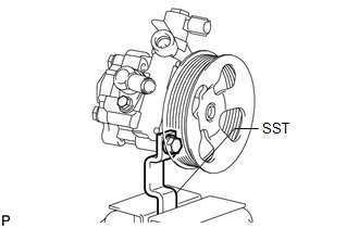
1. SECURE VANE PUMP ASSEMBLY
|
(a) Using SST, secure the vane pump in a vise. SST: 09630-00014 09631-00132 |
|
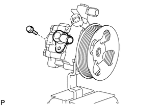
2. REMOVE SUCTION PORT UNION
|
(a) Remove the bolt and suction port union from the vane pump. |
|
(b) Using a screwdriver, remove the O-ring from the suction port union.
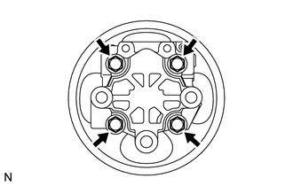
3. REMOVE VANE PUMP REAR HOUSING
|
(a) Remove the 4 bolts and vane pump rear housing from the vane pump front housing. |
|
|
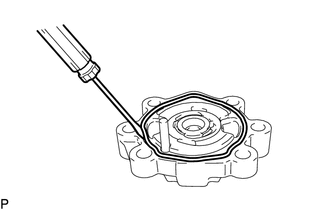
(b) Using a screwdriver, remove the O-ring from the vane pump rear housing. |
|
4. REMOVE VANE PUMP SHAFT WITH PULLEY
|
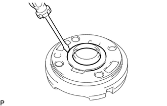
(a) Using 2 screwdrivers, remove the snap ring from the vane pump shaft. |
|
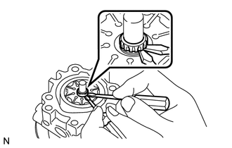
(b) Remove the vane pump shaft with pulley.
NOTICE:
Be careful not to drop or damage the vane pump shaft with vane pump pulley.
If it is damaged, replace the vane pump assembly.
5. REMOVE VANE PUMP ROTOR
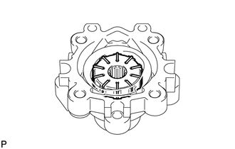
(a) Remove the 10 vane pump plates.
NOTICE:
Take care not to drop the vane pump plates.
(b) Remove the vane pump rotor from the vane pump front housing.
6. REMOVE VANE PUMP CAM RING
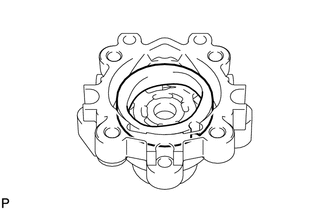
(a) Remove the cam ring from the vane pump front housing.
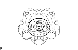
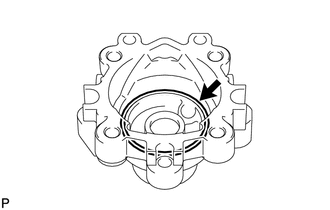
7. REMOVE VANE PUMP FRONT SIDE PLATE
|
(a) Remove the front side plate from the vane pump front housing. |
|
|
(b) Using a screwdriver, remove the O-ring from the front side plate. |
|
|
(c) Remove the O-ring from the vane pump front housing. |
|
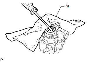
8. REMOVE VANE PUMP HOUSING OIL SEAL
|
(a) Using a screwdriver and piece of cloth, pry out the oil seal. Text in Illustration
NOTICE: Be careful not to damage the vane pump front housing. |
|
 Removal
REMOVAL
CAUTION / NOTICE / HINT
NOTICE:
When using a vise, do not overtighten it.
When installing the parts indicated by arrows, coat them with power
steering fluid (See page ).
...
 Inspection
INSPECTION
PROCEDURE
1. INSPECT VANE PUMP SHAFT AND BUSH IN VANE PUMP FRONT HOUSING
(a) Using a micrometer, measure the outer diameter of the vane pump shaft.
Text in Illustration
...
Other materials about Toyota 4Runner:
Monitor Drive Pattern
MONITOR DRIVE PATTERN
1. TEST MONITOR DRIVE PATTERN FOR ECT
CAUTION:
Perform this drive pattern on a level surface and strictly observe the posted
speed limits and traffic laws while driving.
HINT:
Performing this drive pattern is one method to simulate ...
Lifter Sensor Malfunction (B2653)
DESCRIPTION
When the front power seat switch LH does not receive a sensor signal despite
upward or downward movement of the seat by power seat motor operation, this DTC
is stored.
DTC Code
DTC Detection Condition
Trouble ...

0.0267