Toyota 4Runner: Disassembly
DISASSEMBLY
PROCEDURE
1. REMOVE STEERING LOCK ACTUATOR ASSEMBLY
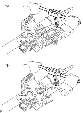
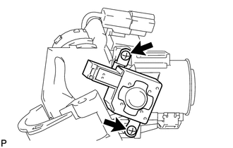
(a) Using a center punch, mark the center of the tapered-head bolt.
(b) Using a 3 to 4 mm (0.118 to 0.157 in.) drill, drill a hole in the 2 bolts.
|
(c) Using a screw extractor, remove the bolt and steering lock actuator assembly from steering column assembly. Text in Illustration
|
|
2. REMOVE IGNITION SWITCH LOCK CYLINDER ASSEMBLY (w/o Smart Key System)
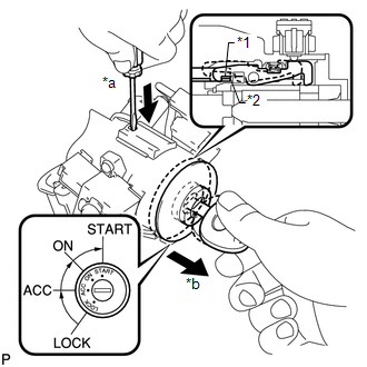
(a) Turn the ignition switch to ON (ACC).
|
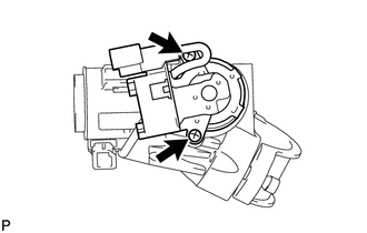
(b) Insert the tip of a screwdriver into the hole in the steering column upper bracket, as shown in the illustration, and pull the ignition switch lock cylinder out until its claw comes into contact with the stopper of the steering column upper bracket. Text in Illustration
NOTICE: Pull the ignition switch lock cylinder assembly out until its claw comes into contact with the stopper of the steering column bracket assembly upper. Otherwise, the following procedure cannot be conducted properly. |
|
|
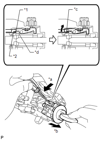
(c) Insert the tip of a screwdriver into the hole in the steering column bracket and tilt it downward, as shown in the illustration, to disengage the claw of the ignition switch lock cylinder. Then pull out the ignition switch lock cylinder. Text in Illustration
|
|
3. REMOVE UNLOCK WARNING SWITCH ASSEMBLY (w/o Smart Key System)
|
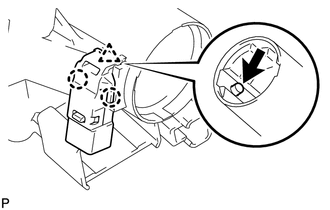
(a) Push up the unlock warning switch center portion to disengage the 2 claws. HINT: Slide the unlock warning switch in the direction shown by the arrow in the illustration to remove it. |
|
4. REMOVE KEY INTERLOCK SOLENOID (w/o Smart Key System)
(a) Disconnect the connector.
|
(b) Remove the 2 screws and remove the key interlock solenoid from the steering column upper bracket. |
|
5. REMOVE IGNITION SWITCH ASSEMBLY (w/o Smart Key System)
|
(a) Remove the 2 screws and remove the ignition switch from the steering column upper bracket. |
|
6. REMOVE KEY INTERLOCK SOLENOID WIRE (w/o Smart Key System)
(a) Remove the key interlock solenoid wire from the ignition switch.
 Removal
REMOVAL
CAUTION / NOTICE / HINT
CAUTION:
Some of these service operations affect the SRS airbag system. Read the precautionary
notices concerning the SRS airbag system before servicing the steeri ...
 Reassembly
REASSEMBLY
PROCEDURE
1. INSTALL KEY INTERLOCK SOLENOID WIRE (w/o Smart Key System)
(a) Install the key interlock solenoid wire on to the install the ignition switch.
2. INSTALL IGNITION SWITCH ASS ...
Other materials about Toyota 4Runner:
Installation
INSTALLATION
PROCEDURE
1. INSTALL OUTER BACK DOOR GLASS WEATHERSTRIP ASSEMBLY
(a) Attach the 8 claws to install the outer back door glass weatherstrip.
2. INSTALL BACK DOOR GLASS
3. INSTALL BACK DOOR GLASS RUN
4. INSTALL NO. 1 BACK WINDOW WIPER MOT ...
Data Signal Circuit between Radio Receiver and Stereo Jack Adapter
DESCRIPTION
The No. 1 stereo jack adapter assembly sends the sound data signal or image data
signal from a USB device to the radio and display receiver assembly via this circuit.
WIRING DIAGRAM
PROCEDURE
1.
CHECK HARNESS AND CONN ...

0.0077