Toyota 4Runner: Disassembly
DISASSEMBLY
PROCEDURE
1. REMOVE FRONT SUSPENSION UPPER ARM BUSH LH
HINT:
Use the same procedure for the front and rear sides.
|
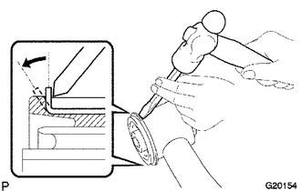
(a) Using a hammer and chisel, strike and bend the entire flange of the upper arm bush as shown in the illustration. |
|
|
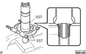
(b) Using SST and a press, press out the bush. SST: 09613-26010 SST: 09710-22021 09710-01031 SST: 09950-00020 |
|
2. REMOVE FRONT UPPER BALL JOINT DUST COVER LH
|
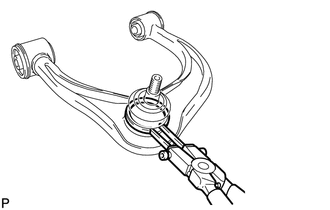
(a) Using a snap ring expander, remove the dust cover set ring and dust cover from the upper arm. NOTICE:
|
|
 On-vehicle Inspection
ON-VEHICLE INSPECTION
PROCEDURE
1. INSPECT FRONT SUSPENSION UPPER ARM BALL JOINT RATTLE
(a) Jack up the vehicle.
(b) Move the front suspension upper arm up and down by hand and check for rattle.
...
 Removal
REMOVAL
CAUTION / NOTICE / HINT
HINT:
Use the same procedure for the RH and LH sides.
The procedure listed below is for the LH side.
PROCEDURE
1. REMOVE FRONT WHEEL
2. REMOVE S ...
Other materials about Toyota 4Runner:
All Power Windows do not Operate with Driver Side Door Key Cylinder or Wireless
Transmitter
DESCRIPTION
When a key switch is pushed: 1) the door control receiver receives the
key signal; 2) the door control receiver sends a signal to the certification
ECU; 3) the main body ECU (multiplex network body ECU) sends the operation
permi ...
Inspection
INSPECTION
PROCEDURE
1. INSPECT REAR NO. 1 SEAT OUTER BELT ASSEMBLY
(a) Check the ELR.
(1) When the inclination of the retractor is 15° or less, check that
the belt can be pulled from the retractor. When the inclination of the retractor
...

0.029