Toyota 4Runner: Headlight Dimmer Switch Circuit
DESCRIPTION
The main body ECU receives the following signals:
- Headlight dimmer switch tail, head, AUTO*, high or high flash signal
- Front fog light switch signal
- *: w/ Automatic Light Control System
WIRING DIAGRAM

PROCEDURE
|
1. |
READ VALUE USING TECHSTREAM (HEADLIGHT DIMMER SWITCH) |
(a) Using the Techstream, read the Data List (See page
.gif) ).
).
Main Body
|
Tester Display |
Measurement Item/Range |
Normal Condition |
Diagnostic Note |
|---|---|---|---|
|
Dimmer SW |
Headlight dimmer switch high signal / ON or OFF |
ON: Headlight dimmer switch in high or high flash OFF: Headlight dimmer switch in low |
- |
|
Passing Light SW |
Headlight dimmer switch high flash signal / ON or OFF |
ON: Headlight dimmer switch in high flash OFF: Headlight dimmer switch not in high flash |
- |
|
Front Fog Light SW |
Front fog light switch signal / ON or OFF |
ON: Front fog light switch on OFF: Front fog light switch off |
- |
|
Auto Light SW* |
Headlight dimmer switch AUTO signal / ON or OFF |
ON: Headlight dimmer switch in AUTO OFF: Headlight dimmer switch not in AUTO |
- |
|
Head Light SW (Head) |
Headlight dimmer switch head signal / ON or OFF |
ON: Headlight dimmer switch in head OFF: Headlight dimmer switch not in head |
- |
|
Head Light SW (Tail) |
Headlight dimmer switch tail signal / ON or OFF |
ON: Headlight dimmer switch in tail or head OFF: Headlight dimmer switch not in tail or head |
- |
- *: w/ Automatic Light Control System
OK:
The display is as specified in the normal condition column.
| OK | .gif) |
PROCEED TO NEXT SUSPECTED AREA SHOWN IN PROBLEM SYMPTOMS TABLE |
|
.gif)
|
2. |
INSPECT HEADLIGHT DIMMER SWITCH ASSEMBLY |
|
(a) Remove the headlight dimmer switch (See page
|
|
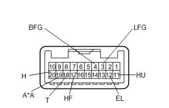
(b) Measure the resistance according to the value(s) in the table below.
Standard Resistance:
|
Tester Connection |
Switch Condition |
Specified Condition |
|---|---|---|
|
4 (BFG) - 3 (LFG) |
Fog light switch on |
Below 1 Ω |
|
11 (HU) - 12 (EL) |
Headlight dimmer switch high |
Below 1 Ω |
|
Headlight dimmer switch high flash |
||
|
17 (HF) - 12 (EL) |
Headlight dimmer switch high flash |
Below 1 Ω |
|
18 (T) - 12 (EL) |
Headlight dimmer switch tail |
Below 1 Ω |
|
Headlight dimmer switch head |
||
|
19 (A) - 12 (EL)* |
Headlight dimmer switch AUTO |
Below 1 Ω |
|
20 (H) - 12 (EL) |
Headlight dimmer switch head |
Below 1 Ω |
|
4 (BFG) - 3 (LFG) |
Fog light switch off |
10 kΩ or higher |
|
18 (T) - 12 (EL) |
Headlight dimmer switch off |
10 kΩ or higher |
|
19 (A) - 12 (EL)* |
||
|
20 (H) - 12 (EL) |
- *: w/ Automatic Light Control System
|
*A |
w/ Automatic Light Control System |
| NG | |
REPLACE HEADLIGHT DIMMER SWITCH ASSEMBLY |
|
|
3. |
CHECK HARNESS AND CONNECTOR (HEADLIGHT DIMMER SWITCH ASSEMBLY - MAIN BODY ECU AND BODY GROUND) |
(a) Disconnect the F22 headlight dimmer switch connector.
(b) Disconnect the F9 main body ECU connector.
(c) Measure the resistance according to the value(s) in the table below.
Standard Resistance:
|
Tester Connection |
Condition |
Specified Condition |
|---|---|---|
|
F22-4 (BFG) - F9-27 (FFOG) |
Always |
Below 1 Ω |
|
F22-11 (HU) - F9-5 (HU) |
Always |
Below 1 Ω |
|
F22-17 (HF) - F9-8 (HF) |
Always |
Below 1 Ω |
|
F22-18 (T) - F9-30 (TAIL) |
Always |
Below 1 Ω |
|
F22-19 (A) - F9-28 (A)* |
Always |
Below 1 Ω |
|
F22-20 (H) - F9-29 (HEAD) |
Always |
Below 1 Ω |
|
F22-4 (BFG) - Body ground |
Always |
10 kΩ or higher |
|
F22-11 (HU) - Body ground |
Always |
10 kΩ or higher |
|
F22-17 (HF) - Body ground |
Always |
10 kΩ or higher |
|
F22-18 (T) - Body ground |
Always |
10 kΩ or higher |
|
F22-19 (A) - Body ground* |
Always |
10 kΩ or higher |
|
F22-20 (H) - Body ground |
Always |
10 kΩ or higher |
|
F22-12 (EL) - Body ground |
Always |
Below 1 Ω |
|
F22-3 (LFG) - Body ground |
Always |
Below 1 Ω |
- *: w/ Automatic Light Control System
| OK | |
REPLACE MAIN BODY ECU (MULTIPLEX NETWORK BODY ECU) |
| NG | |
REPAIR OR REPLACE HARNESS OR CONNECTOR |
 Light Sensor Circuit Malfunction (B1244)
DESCRIPTION
The automatic light control sensor detects ambient light, converts it into an
electrical signal, and outputs it to the main body ECU. The main body ECU turns
on or off the headlights ...
 Headlight Relay Circuit
DESCRIPTION
The main body ECU receives headlight dimmer switch information signals, and illuminates
the low beam headlight.
WIRING DIAGRAM
CAUTION / NOTICE / HINT
NOTICE:
Inspect the fuses an ...
Other materials about Toyota 4Runner:
Pressure Sensor or Switch (C1254)
DESCRIPTION
The accumulator pressure sensor is connected to the skid control ECU in the master
cylinder solenoid.
DTC Code
DTC Detection Condition
Trouble Area
C1254
There is an accumulator pre ...
Fuel Receiver Gauge Malfunction
DESCRIPTION
The fuel sender gauge has a variable resistance mechanism. The resistance
decreases when the fuel amount increases, and the resistance increases when
the fuel amount decreases. The fuel receiver gauge changes based on the
resist ...

0.0212