Toyota 4Runner: Disassembly
DISASSEMBLY
CAUTION / NOTICE / HINT
HINT:
- Use the same procedure for the RH and LH sides.
- The procedure listed below is for the LH side.
PROCEDURE
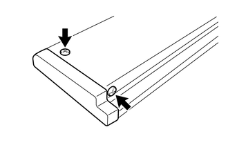
1. REMOVE STEP PLATE COVER LH
|
(a) Remove the 2 screws and step plate cover LH. |
|
2. REMOVE STEP PLATE COVER RH
HINT:
Use the same procedure as described for the step plate cover LH.
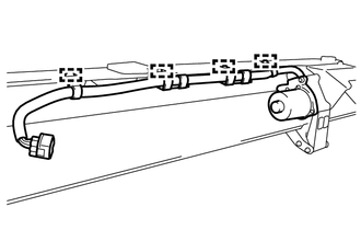
3. REMOVE SIDE AUTO STEP MOTOR ASSEMBLY
|
(a) Disengage the 4 clamps. |
|
|
(b) Remove the bolt. |
|
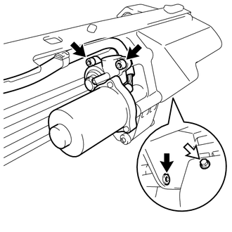
(c) Using a 6 mm hexagon wrench, remove the 3 hexagon bolts and side auto step motor assembly.
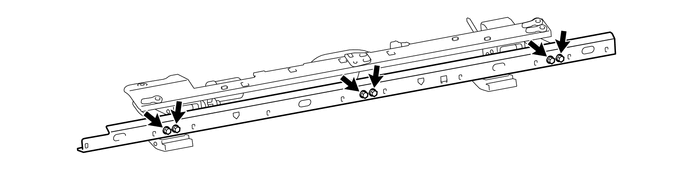
4. REMOVE FLOOR SIDE SILL STAY
(a) Remove the 6 bolts and floor side sill stay.
 Removal
REMOVAL
CAUTION / NOTICE / HINT
HINT:
Use the same procedure for the RH and LH sides.
The procedure listed below is for the LH side.
PROCEDURE
1. REMOVE ROCKER PANEL MOULDING (w ...
 Inspection
INSPECTION
PROCEDURE
1. INSPECT SIDE AUTO STEP MOTOR ASSEMBLY
(a) Check that the motor gear rotates smoothly as follows.
NOTICE:
Do not apply positive (+) battery voltage to any te ...
Other materials about Toyota 4Runner:
System Description
SYSTEM DESCRIPTION
1. NAVIGATION SYSTEM OUTLINE
(a) Vehicle position tracking methods
It is essential that the navigation system correctly tracks the current vehicle
position and displays it on the map. There are 2 methods to track the current vehicle
p ...
Removal
REMOVAL
PROCEDURE
1. DISCONNECT CABLE FROM NEGATIVE BATTERY TERMINAL
CAUTION:
Wait at least 90 seconds after disconnecting the cable from the negative (-)
battery terminal to disable the SRS system (See page
).
NOTICE:
When disconnecting the cable, s ...

0.0069