Toyota 4Runner: Inspection
INSPECTION
PROCEDURE
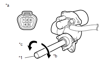
1. INSPECT SIDE AUTO STEP MOTOR ASSEMBLY
|
(a) Check that the motor gear rotates smoothly as follows. NOTICE: Do not apply positive (+) battery voltage to any terminals except terminal 5 and 4 to avoid damaging the pulse sensor inside the motor. OK:
CAUTION: Reset the side auto step motor assembly (initialize the pulse sensor) after installing the side auto step motor assembly and side auto step assembly. Text in Illustration
|
|
 Disassembly
DISASSEMBLY
CAUTION / NOTICE / HINT
HINT:
Use the same procedure for the RH and LH sides.
The procedure listed below is for the LH side.
PROCEDURE
1. REMOVE STEP PLATE COVER LH
...
 Installation
INSTALLATION
CAUTION / NOTICE / HINT
HINT:
Use the same procedure for the RH and LH sides.
The procedure listed below is for the LH side.
PROCEDURE
1. INSTALL POWER LIFT STEP AS ...
Other materials about Toyota 4Runner:
Automatic door locking and unlocking systems
The following functions can be set or canceled:
Setting and canceling the functions
To switch between setting and canceling, follow the procedure below:
Vehicles without a smart key system
Close all the doors and turn the engine switch to the “ON†...
Data List / Active Test
DATA LIST / ACTIVE TEST
1. READ DATA LIST
HINT:
Using the Techstream to read the Data List allows values or states of switches,
sensors, actuators and other items to be read without removing any parts. This non-intrusive
inspection can be very useful be ...

0.0137