Toyota 4Runner: Terminals Of Ecu
TERMINALS OF ECU
1. CHECK POWER MANAGEMENT CONTROL ECU
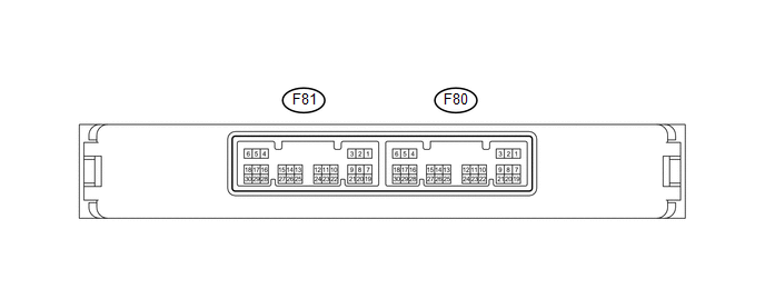
(a) Disconnect the F80 power management control ECU connector.
(b) Measure the voltage and resistance according to the value(s) in the table below.
|
Terminal No. (Symbol) |
Wiring Color |
Terminal Description |
Condition |
Specified Condition |
|---|---|---|---|---|
|
F80-1 (AM22) - Body ground |
B - Body ground |
+B power supply |
Always |
9.5 to 14 V |
|
F80-2 (AM21) - Body ground |
B - Body ground |
+B power supply |
Always |
9.5 to 14 V |
|
F80-5 (GND2) - Body ground |
W-B - Body ground |
Ground |
Always |
Below 1 Ω |
|
F80-6 (GND) - Body ground |
W-B - Body ground |
Ground |
Always |
Below 1 Ω |
|
F80-17 (SSW2) - Body ground |
R - Body ground |
Engine switch signal |
Engine switch pushed |
Below 1 Ω |
|
F80-17 (SSW2) - Body ground |
R - Body ground |
Engine switch signal |
Engine switch not pushed |
10 kΩ or higher |
|
F80-18 (SSW1) - Body ground |
LG - Body ground |
Engine switch signal |
Engine switch pushed |
Below 1 Ω |
|
F80-18 (SSW1) - Body ground |
LG - Body ground |
Engine switch signal |
Engine switch not pushed |
10 kΩ or higher |
|
F80-24 (LIN2) - Body ground |
G - Body ground |
LIN line |
Always |
10 kΩ or higher |
If the result is not as specified, there may be a malfunction on the wire harness side.
(c) Reconnect the F80 power management control ECU connector.
(d) Measure the voltage according to the value(s) in the table below.
|
Terminal No. (Symbol) |
Wiring Color |
Terminal Description |
Condition |
Specified Condition |
|---|---|---|---|---|
|
F80-3 (SLP) - F80-6 (GND) |
SB - W-B |
Steering lock actuator position signal |
Steering lock released |
Pulse generation (See waveform 1) |
|
F80-3 (SLP) - F80-6 (GND) |
SB - W-B |
Steering lock actuator position signal |
Steering lock locked |
Pulse generation (See waveform 1) |
|
F80-8 (SLR+) - F80-6 (GND) |
GR - W-B |
Steering lock motor signal |
Steering lock motor operating |
Below 1 V |
|
F80-8 (SLR+) - F80-6 (GND) |
GR - W-B |
Steering lock motor signal |
Steering lock motor not operating |
11 to 14 V |
|
F80-10 (INDW) - F80-6 (GND) |
L - W-B |
Warning signal |
|
8 to 14 V |
|
F80-16 (P) - F80-6 (GND) |
V - W-B |
Shift lock signal |
Shift lever in P |
8 to 14 V |
|
F80-16 (P) - F80-6 (GND) |
V - W-B |
Shift lock signal |
Shift lever not in P |
Below 1 V |
|
F80-19 (ACCD) - F80-6 (GND) |
R - W-B |
ACC signal |
Engine switch on (ACC) |
8 to 14 V |
|
F80-19 (ACCD) - F80-6 (GND) |
R - W-B |
ACC signal |
Engine switch off |
Below 1 V |
|
F80-20 (IG1D) - F80-6 (GND) |
V - W-B |
IG1 signal |
Engine switch on (IG) |
8 to 14 V |
|
F80-20 (IG1D) - F80-6 (GND) |
V - W-B |
IG1 signal |
Engine switch on (ACC) |
Below 1 V |
|
F80-22 (INDS) - F80-6 (GND) |
B - W-B |
Vehicle condition signal |
|
8 to 14 V |
|
F80-23 (SPD) - F80-6 (GND) |
SB - W-B |
Vehicle speed signal |
Engine switch on (IG), vehicle being driven at approx. 20 km/h (12 mph) |
Pulse generation (See waveform 2) |
|
F81-2 (STA) - F80-6 (GND) |
W - W-B |
Park/neutral position switch signal |
Shift lever in P or N |
Below 1 V |
|
F81-3 (STAR) - F80-6 (GND) |
B - W-B |
Starter signal |
|
8 to 14 V* |
|
F81-8 (IG2D) - F80-6 (GND) |
L - W-B |
IG2 signal |
Engine switch on (IG) |
8 to 14 V |
|
F81-8 (IG2D) - F80-6 (GND) |
L - W-B |
IG2 signal |
Engine switch on (ACC) |
Below 1 V |
|
F81-11 (STP1) - F80-6 (GND) |
V - W-B |
Stop light signal |
Brake pedal depressed |
8 to 14 V |
|
F81-11 (STP1) - F80-6 (GND) |
V - W-B |
Stop light signal |
Brake pedal released |
Below 1 V |
- *: Voltage is output for 0.3 seconds when the engine is cranking. Disconnect the connector from the ECM before measuring the voltage.
If the result is not as specified, the ECU may have a malfunction.
(e) Using an oscilloscope, check the signal waveform of the ECU.
(1) Waveform 1
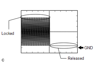 Waveform 1 (Reference)
|
Terminal No. (Symbol) |
F80-3 (SLP) - F80-6 (GND) |
|
Tool Setting |
2 V/DIV., 100 ms./DIV. |
|
Vehicle Condition |
Steering lock locked or released |
(2) Waveform 2
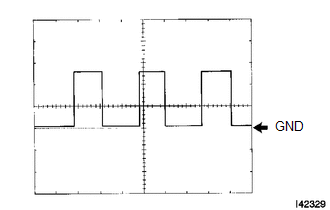 Waveform 2 (Reference)
|
Terminal No. (Symbol) |
F80-23 (SPD) - F80-6 (GND) |
|
Tool Setting |
5 V/DIV., 10 ms./DIV. |
|
Vehicle Condition |
Engine switch on (IG), vehicle being driven at approx. 5 km/h (3 mph) |
HINT:
As the vehicle speed increases, the wavelength shortens.
2. CHECK CERTIFICATION ECU
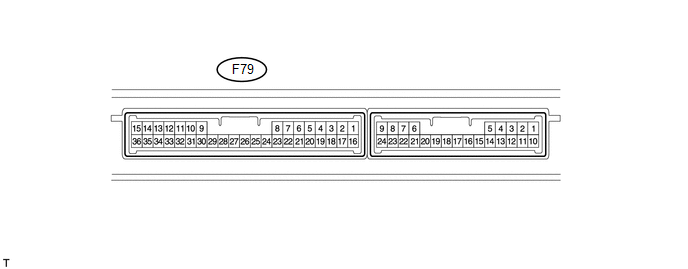
(a) Disconnect the F79 certification ECU connector.
(b) Measure the voltage and resistance according to the value(s) in the table below.
|
Terminal No. (Symbol) |
Wiring Color |
Terminal Description |
Condition |
Specified Condition |
|---|---|---|---|---|
|
F79-1 (+B) - Body ground |
V - Body ground |
+B power supply |
Always |
11 to 14 V |
|
F79-15 (E) - Body ground |
W-B - Body ground |
Ground |
Always |
Below 1 Ω |
|
F79-29 (LIN) - Body ground |
G - Body ground |
LIN line |
Always |
10 kΩ or higher |
If the result is not as specified, there may be a malfunction on the wire harness side.
3. CHECK STEERING LOCK ECU
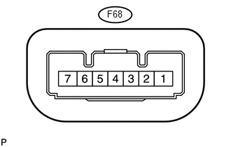
(a) Disconnect the F68 steering lock ECU connector.
(b) Measure the voltage and resistance according to the value(s) in the table below.
|
Terminal No. (Symbol) |
Wiring Color |
Terminal Description |
Condition |
Specified Condition |
|---|---|---|---|---|
|
F68-1 (GND) - Body ground |
W-B - Body ground |
Ground |
Always |
Below 1 Ω |
|
F68-6 (IG2) - Body ground |
W - Body ground |
Ignition power supply |
Engine switch on (IG) |
11 to 14 V |
|
F68-6 (IG2) - Body ground |
W - Body ground |
Ignition power supply |
Engine switch off |
Below 1 V |
|
F68-7 (B) - Body ground |
GR - Body ground |
+B power supply |
Always |
11 to 14 V |
- If the result is not as specified, there may be a malfunction on the wire harness side.
(c) Reconnect the F68 steering lock ECU connector.
(d) Measure the voltage according to the value(s) in the table below.
|
Terminal No. (Symbol) |
Wiring Color |
Terminal Description |
Condition |
Specified Condition |
|---|---|---|---|---|
|
F68-4 (SLP1) - F68-1 (GND) |
SB - W-B |
Steering lock actuator position signal |
Steering lock locked |
11 to 14 V |
|
F68-4 (SLP1) - F68-1 (GND) |
SB - W-B |
Steering lock actuator position signal |
Steering lock released |
Below 1 V |
- If the result is not as specified, the ECU may have a malfunction.
 Problem Symptoms Table
PROBLEM SYMPTOMS TABLE
HINT:
Use the table below to help determine the cause of problem symptoms.
If multiple suspected areas are listed, the potential causes of the symptoms
are lis ...
 Data List / Active Test
DATA LIST / ACTIVE TEST
1. READ DATA LIST
HINT:
Using the Techstream to read the Data List allows the values or states of switches,
sensors, actuators and other items to be read without removing ...
Other materials about Toyota 4Runner:
Inspection
INSPECTION
PROCEDURE
1. INSPECT HOOD LOCK ASSEMBLY (ENGINE HOOD COURTESY SWITCH)
(a) Measure the resistance according to the value(s) in the table below.
Standard Resistance:
Tester Connection
Condition
Specified Condit ...
Bleeding
BLEEDING
PROCEDURE
1. BLEED AIR FROM SUSPENSION FLUID
CAUTION:
Be sure to check the pipe connections and whether or not any hydraulic
circuit parts are damaged before performing work as the hydraulic circuits
become highly pressurized durin ...

0.0071