Toyota 4Runner: Disassembly
DISASSEMBLY
PROCEDURE
1. REMOVE REAR BUMPER LOWER COVER (w/ Garnish)
|
(a) Remove the 2 clips and 14 outside moulding retainers. |
|
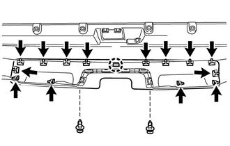
(b) Detach the claw to remove the rear bumper lower cover
2. REMOVE REAR BUMPER EXTENSION (w/o Pintle Hook)
|
(a) Remove the 2 clips and 2 outside moulding retainers. |
|
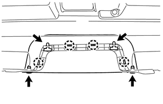
(b) Detach the 4 claws to remove the rear bumper extension.
3. REMOVE REAR BUMPER EXTENSION (w/ Pintle Hook)
|
(a) Remove the 2 clips and 2 outside moulding retainers. |
|
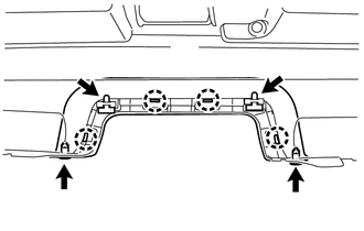
(b) Detach the 4 claws to remove the rear bumper extension.
4. REMOVE REAR BUMPER SIDE BRACKET LH
|
(a) Remove the clip and 2 screws. |
|
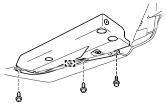
(b) Detach the guide to remove the rear bumper side bracket LH.
5. REMOVE REAR BUMPER SIDE BRACKET RH
HINT:
Use the same procedure as for the LH side.
 Removal
REMOVAL
PROCEDURE
1. REMOVE JACK BOX HOLE COVER
(a) Put protective around the jack box hole cover.
(b) Using a moulding remover, Detach th ...
 Reassembly
REASSEMBLY
PROCEDURE
1. INSTALL REAR BUMPER SIDE BRACKET LH
(a) Attach the guide.
(b) Install the rear bumper side bracket LH with the 2 screws and clip.
2. INSTALL REAR BUMPER SIDE BRACKET RH
H ...
Other materials about Toyota 4Runner:
Disassembly
DISASSEMBLY
PROCEDURE
1. SECURE VANE PUMP ASSEMBLY
(a) Using SST, secure the vane pump in a vise.
SST: 09630-00014
09631-00132
2. REMOVE SUCTION PORT UNION
(a) Remove the bolt and ...
Trailer towing
Your vehicle is designed primarily as a passenger-and-load-carrying
vehicle. Towing a trailer can have an adverse impact on handling, performance,
braking, durability, and fuel consumption. For your safety and the safety of
others, you must not overload ...

0.0075