Toyota 4Runner: Disassembly
DISASSEMBLY
PROCEDURE
1. REMOVE NO. 1 POWER OUTLET SOCKET ASSEMBLY
.gif)
2. REMOVE NO. 1 POWER OUTLET SOCKET COVER
3. REMOVE REAR CONSOLE END PANEL
|
(a) Detach the 4 clips and 4 claws to remove the rear console end panel. |
|
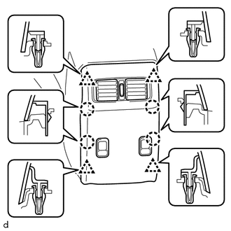
(b) Disconnect the 2 power outlet socket assembly connectors.
4. REMOVE NO. 3 POWER OUTLET SOCKET ASSEMBLY
5. REMOVE CENTER POWER OUTLET SOCKET COVER
6. REMOVE CONSOLE BOX REGISTER ASSEMBLY
|
(a) Detach the 4 claws to remove the console box register assembly. |
|
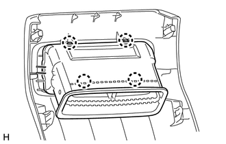
7. REMOVE CONSOLE COMPARTMENT DOOR SUB-ASSEMBLY
|
(a) Remove the 6 screws and console compartment door sub-assembly. |
|
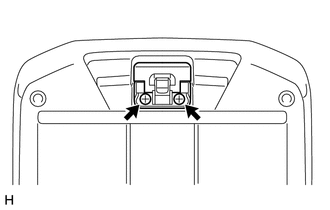
8. REMOVE CONSOLE COMPARTMENT DOOR LOCK SUB-ASSEMBLY
|
(a) Remove the 2 screws and console compartment door lock sub-assembly. |
|
9. REMOVE CONSOLE COMPARTMENT DOOR HINGE SUB-ASSEMBLY
|
(a) Remove the 4 screws. |
|
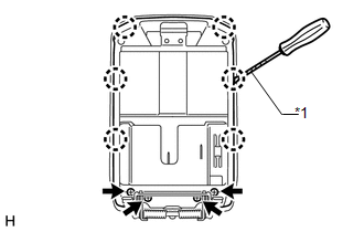
(b) Using a screwdriver, detach the 6 claws to remove the console compartment inner door.
Text in Illustration|
*1 |
Protective Tape |
HINT:
Tape the screwdriver tip before use.
|
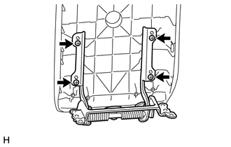
(c) Remove the 4 screws and console compartment door hinge sub-assembly. |
|
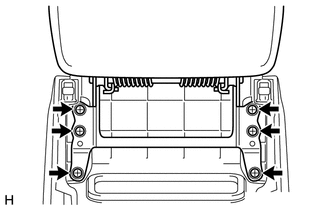
10. REMOVE CONSOLE CUP HOLDER BOX
|
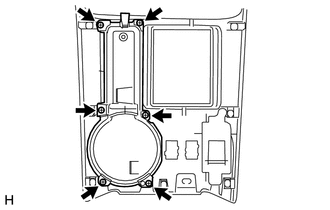
(a) Remove the 6 screws and console cup holder box. |
|
11. REMOVE BACK DOOR POWER WINDOW REGULATOR SWITCH ASSEMBLY
12. REMOVE SEAT HEATER SWITCH (w/ Seat Heater System)
13. REMOVE SWITCH BASE
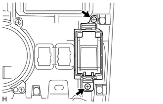
|
(a) Remove the 2 screws and switch base. |
|
14. REMOVE SHIFTING HOLE COVER SUB-ASSEMBLY (for VF2A)
|
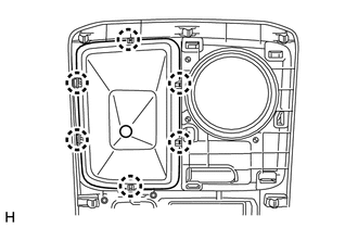
(a) Detach the 6 claws to remove the shifting hole cover sub-assembly. |
|
15. REMOVE FRONT UPPER CONSOLE PANEL GARNISH
(a) for VF2A:
|
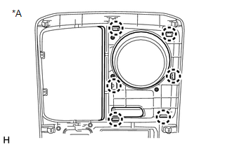
(1) Detach the 6 claws to remove the front upper console panel garnish. Text in Illustration
|
|
(b) for 2WD, for VF2BM, VF4BM:
(1) Detach the 10 claws to remove the front upper console panel garnish.
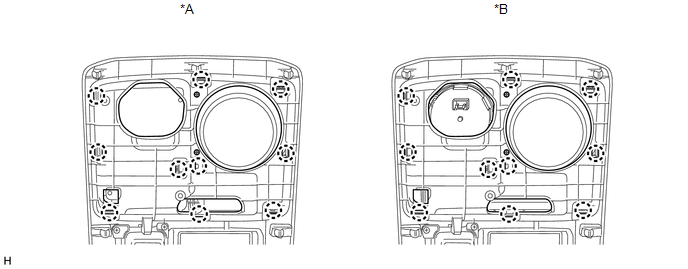 Text in Illustration
|
*A |
for 2WD |
*B |
for VF2BM, VF4BM |
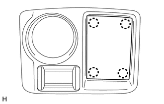
16. REMOVE NO. 2 BOX BOTTOM MAT (for 2WD)
|
(a) Detach the 4 claws to remove the No. 2 box bottom mat. |
|
17. REMOVE TRANSFER POSITION SWITCH (for VF2BM)
18. REMOVE TRANSFER POSITION SWITCH (for VF4BM)
 Components
COMPONENTS
ILLUSTRATION
ILLUSTRATION
ILLUSTRATION
ILLUSTRATION
...
 Removal
REMOVAL
PROCEDURE
1. REMOVE NO. 1 INSTRUMENT CLUSTER FINISH PANEL GARNISH
(a) Put protective tape around the No. 1 instrument cluster finish panel garnish.
(b) Grip the No. 1 instrument cluster fi ...
Other materials about Toyota 4Runner:
Reassembly
REASSEMBLY
CAUTION / NOTICE / HINT
HINT:
Use the same procedure for both the RH and LH sides.
The procedure listed below is for the LH side.
PROCEDURE
1. INSTALL OUTER MIRROR LIGHT ASSEMBLY BULB (w/ Side Turn Signal Light)
(a) Install t ...
Inspection
INSPECTION
PROCEDURE
1. INSPECT SHIFT SOLENOID VALVE SR
(a) Measure the resistance according to the value(s) in the table below.
Standard Resistance:
Tester Connection
Condition
Specified Condition
Shif ...

0.028