Toyota 4Runner: Disassembly
DISASSEMBLY
PROCEDURE
1. REMOVE TRANSMISSION CONTROL SHAFT LEVER LH
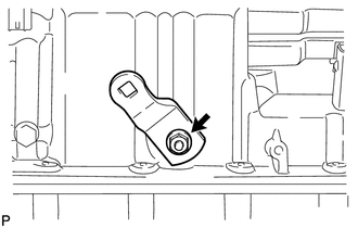
(a) Remove the nut, spring washer and control shaft lever LH.
2. REMOVE PARK/NEUTRAL POSITION SWITCH ASSEMBLY
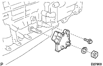
(a) Using a screwdriver, bend the tabs of the lock washer.
(b) Remove the nut, lock washer and bolt.
(c) Remove the park/neutral position switch.
3. REMOVE OIL COOLER TUBE UNION
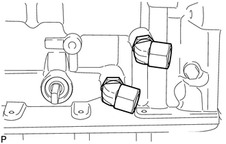
(a) Remove the 2 oil cooler tube unions.
(b) Remove the 2 O-rings from the oil cooler tube unions.
4. REMOVE SPEED SENSOR
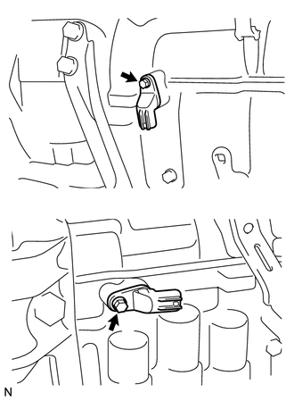
(a) Remove the 2 bolts and 2 speed sensors.
(b) Remove the 2 O-rings from the sensors.
5. REMOVE AUTOMATIC TRANSMISSION BREATHER TUBE
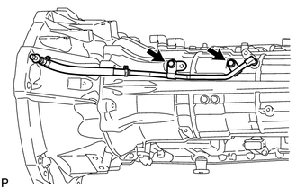
(a) Remove the 2 bolts.
(b) Remove the breather tube.
(c) Remove the O-ring from the tube.
6. REMOVE AUTOMATIC TRANSMISSION HOUSING
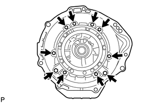
(a) Remove the 10 bolts.
(b) Remove the transmission housing.
7. REMOVE EXTENSION HOUSING SUB-ASSEMBLY
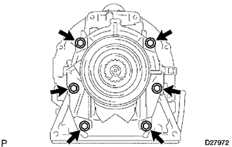
(a) Remove the 6 bolts.
(b) Remove the extension housing.
HINT:
Use a brass bar and hammer to remove the extension housing.
|
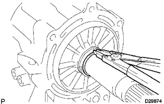
(c) Using a snap ring expander, remove the snap ring. |
|
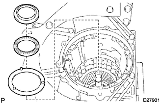
(d) Remove the thrust needle roller bearing and 2 bearing races.
(e) Remove the 2 transfer case ring pins from the transmission case adapter.
8. REMOVE EXTENSION HOUSING DUST DEFLECTOR
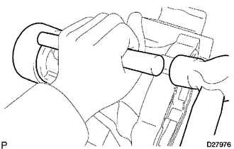
(a) Using a brass bar and hammer, tap out the dust deflector.
9. REMOVE AUTOMATIC TRANSMISSION EXTENSION HOUSING OIL SEAL
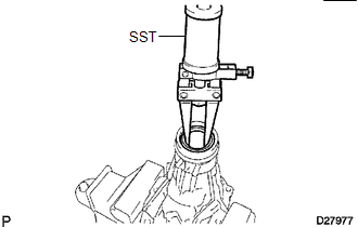
(a) Using SST, tap out the oil seal.
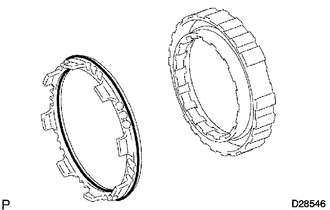
SST: 09308-00010
10. FIX AUTOMATIC TRANSMISSION CASE SUB-ASSEMBLY
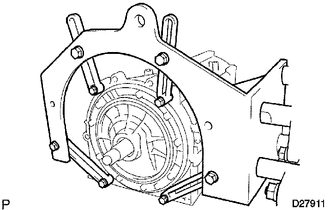
(a) Install the transmission case to an overhaul attachment.
11. REMOVE AUTOMATIC TRANSMISSION OIL PAN SUB-ASSEMBLY
NOTICE:
Do not turn the transmission over as this will contaminate the valve body with foreign matter in the bottom of the pan.
(a) Remove the drain plug and 20 bolts.
(b) Remove the 4 magnets from the oil pan.
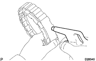
12. INSPECT AUTOMATIC TRANSMISSION OIL PAN SUB-ASSEMBLY
.gif)
13. REMOVE VALVE BODY OIL STRAINER ASSEMBLY
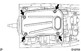
(a) Turn over the transmission.
(b) Remove the 4 bolts and oil strainer from the valve body.
(c) Remove the O-ring from the oil strainer.
14. REMOVE TRANSMISSION WIRE
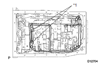
(a) Remove the 2 bolts and 2 temperature sensor clamps, and disconnect the 2 ATF temperature sensors.
Text in Illustration|
*1 |
Temperature Sensor Clamp |
(b) Disconnect the 7 connectors from the solenoid valves.
|
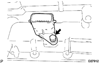
(c) Remove the bolt from the case. |
|
(d) Pull the transmission wire out of the transmission case to remove it.
(e) Remove the O-ring from the transmission wire.
15. REMOVE TRANSMISSION VALVE BODY ASSEMBLY
(a) Remove the bolt, detent spring cover and detent spring.
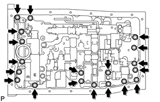
|
(b) Remove the 19 bolts and valve body. |
|
16. REMOVE TRANSMISSION CASE GASKET
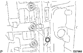
(a) Remove the 3 gaskets.
17. REMOVE BRAKE DRUM GASKET
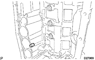
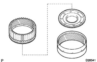
(a) Remove the 3 gaskets.
18. REMOVE CHECK BALL BODY
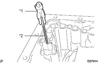
(a) Remove the check ball body and spring.
Text in Illustration|
*1 |
Check Ball Body |
|
*2 |
Spring |
19. REMOVE C-2 ACCUMULATOR PISTON
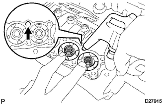
(a) Apply compressed air to the oil hole to remove the C-2 accumulator piston and spring.
(b) Remove the 2 O-rings from the piston.
NOTICE:
Be careful as the C-3 and B-3 accumulator pistons may jump out.
20. REMOVE B-3 ACCUMULATOR PISTON

(a) Apply compressed air to the oil hole to remove the B-3 accumulator piston and spring.
(b) Remove the 2 O-rings from the piston.
NOTICE:
Be careful as the C-3 accumulator piston may jump out.
21. REMOVE C-3 ACCUMULATOR PISTON
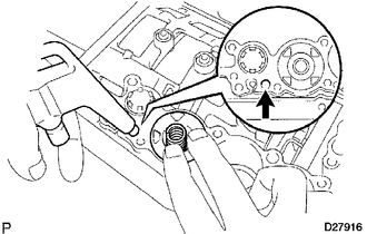
(a) Apply compressed air to the oil hole to remove the C-3 accumulator piston and 2 springs.
(b) Remove the 2 O-rings from the piston.
22. REMOVE C-1 ACCUMULATOR VALVE
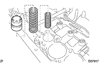
(a) Remove the C-1 accumulator valve and 2 springs.
23. REMOVE PARKING LOCK PAWL BRACKET
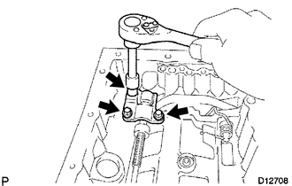
(a) Remove the 3 bolts and bracket.
24. REMOVE PARKING LOCK ROD SUB-ASSEMBLY
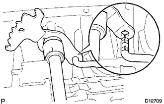
(a) Disconnect the parking lock rod from the manual valve lever to remove it.
25. REMOVE PARKING LOCK PAWL SHAFT
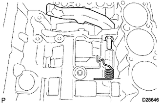
(a) Pull out the parking lock pawl shaft from the front side to remove it, and then remove the lock pawl and spring.
(b) Remove the E-ring from the shaft.
26. REMOVE MANUAL VALVE LEVER SUB-ASSEMBLY
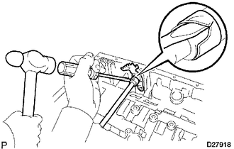
(a) Using a hammer and screwdriver, cut off the spacer and remove it from the shaft.
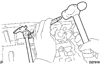
|
(b) Using a pin punch and hammer, tap out the spring pin. HINT: Slowly drive out the spring pin so that it does not fall into the transmission case. |
|
(c) Pull the manual valve lever shaft out through the case and remove the manual valve lever.
27. REMOVE MANUAL VALVE LEVER SHAFT OIL SEAL
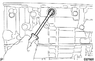
(a) Using a screwdriver, pry out the 2 oil seals.
HINT:
Tape the screwdriver tip before use.
NOTICE:
Be careful not to damage the transmission case.
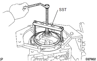
28. REMOVE OIL PUMP ASSEMBLY
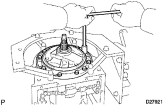
(a) Remove the 10 bolts.
|
(b) Using SST, remove the oil pump. SST: 09350-30020 09350-07020 |
|
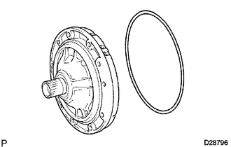
|
(c) Remove the O-ring from the front oil pump. |
|
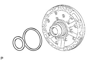
|
(d) Remove the 2 thrust bearing races from the front oil pump. |
|
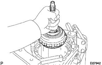
29. REMOVE CLUTCH DRUM AND INPUT SHAFT ASSEMBLY
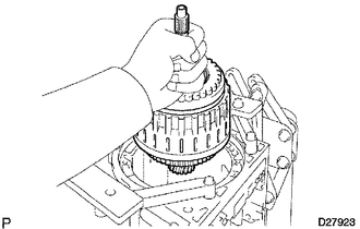
(a) Remove the clutch drum and input shaft assembly from the transmission case.
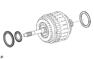
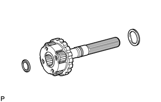
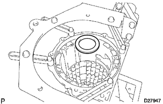
|
(b) Remove the clutch drum thrust washer and 2 thrust needle roller bearings. |
|
30. INSPECT NO. 2 1-WAY CLUTCH ASSEMBLY
.gif)
31. REMOVE NO. 2 1-WAY CLUTCH ASSEMBLY
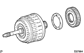
(a) Remove the 1-way clutch and No. 2 clutch drum thrust washer from the clutch drum and input shaft assembly.
32. FIX CLUTCH DRUM AND INPUT SHAFT ASSEMBLY
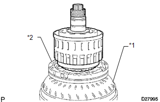
(a) Place the oil pump onto the torque converter clutch, and then place the clutch drum and input shaft assembly onto the oil pump.
Text in Illustration|
*1 |
Torque Converter Clutch |
|
*2 |
Oil Pump |
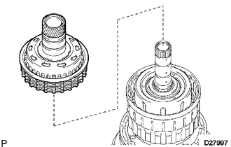
33. REMOVE REVERSE CLUTCH HUB SUB-ASSEMBLY
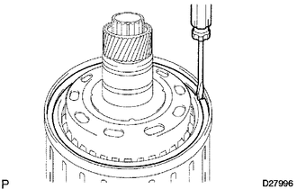
(a) Using a screwdriver, remove the snap ring.
|
(b) Remove the reverse clutch hub sub-assembly, reverse clutch reaction sleeve, clutch cushion, plate reverse clutch flange, 5 reverse clutch discs and 4 clutch plates from the clutch drum. |
|
34. REMOVE REVERSE CLUTCH REACTION SLEEVE
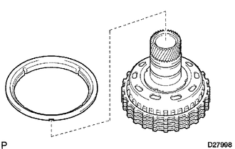
(a) Remove the reverse clutch reaction sleeve from the reverse clutch hub.
35. REMOVE REAR CLUTCH DISC
(a) Remove the clutch cushion plate, reverse clutch flange, 5 discs and 4 plates from the reverse clutch hub.
36. INSPECT REAR CLUTCH DISC
.gif)
37. INSPECT REVERSE CLUTCH HUB SUB-ASSEMBLY
.gif)
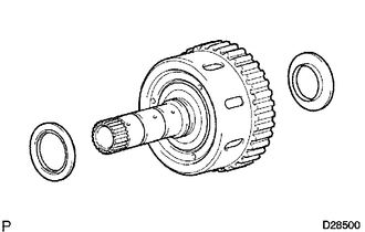
38. REMOVE FORWARD CLUTCH HUB SUB-ASSEMBLY
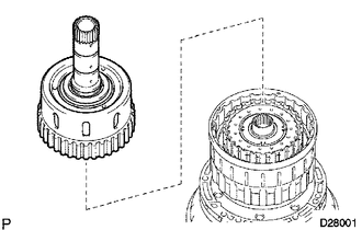
(a) Remove the forward clutch hub from the clutch drum.
|
(b) Remove the 2 thrust needle roller bearings from the forward clutch hub. |
|
39. INSPECT FORWARD CLUTCH HUB SUB-ASSEMBLY
.gif)
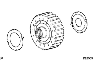
40. REMOVE MULTIPLE DISC CLUTCH HUB
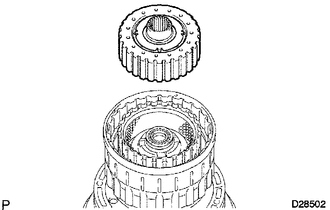
(a) Remove the multiple disc clutch hub from the clutch drum.
|
(b) Remove the 2 thrust bearing races from the multiple disc clutch hub. |
|
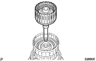
41. REMOVE INPUT SHAFT ASSEMBLY
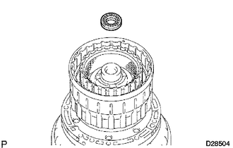
(a) Remove the thrust needle roller bearing from the clutch drum.
|
(b) Remove the input shaft assembly from the clutch drum. |
|
42. REMOVE INPUT SHAFT OIL SEAL RING
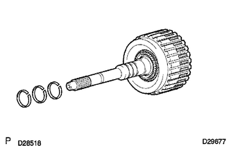
(a) Remove the 3 oil seal rings from the input shaft.
43. REMOVE FORWARD MULTIPLE DISC CLUTCH DISC
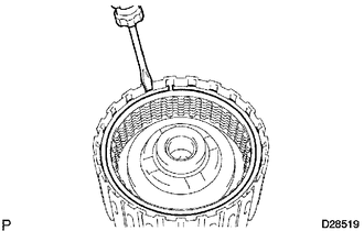
(a) Using a screwdriver, remove the hole snap ring.
(b) Remove the 2 flanges, 6 discs and 5 plates from the input shaft.
44. INSPECT FORWARD MULTIPLE DISC CLUTCH DISC
.gif)
45. REMOVE NO. 1 CLUTCH BALANCER
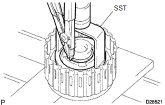
(a) Place SST on the clutch balancer and compress the return spring with a press.
SST: 09350-30020
09350-07040
09350-07070
(b) Using a snap ring expander, remove the snap ring.
|
(c) Remove the clutch balancer and forward clutch return spring from the input shaft assembly. |
|
|
(d) Remove the O-ring from the No. 1 clutch balancer. |
|
46. INSPECT FORWARD CLUTCH RETURN SPRING SUB-ASSEMBLY
.gif)
47. REMOVE FORWARD CLUTCH PISTON
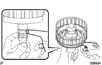
(a) Hold the input shaft by hand and apply compressed air (392 kPa (4.0 kgf/cm2, 57 psi)) to the input shaft to remove the forward clutch piston.
|
(b) Remove the 2 O-rings from the forward clutch piston. |
|
48. REMOVE REVERSE CLUTCH FLANGE
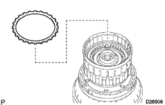
(a) Remove the reverse clutch flange from the clutch drum.
49. REMOVE DIRECT CLUTCH DISC
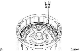
(a) Using a screwdriver, remove the 2 hole snap rings from the clutch drum.
(b) Remove the reverse clutch flange, 5 discs and 5 plates from the clutch drum.
50. INSPECT DIRECT CLUTCH DISC
.gif)
51. REMOVE NO. 3 CLUTCH BALANCER
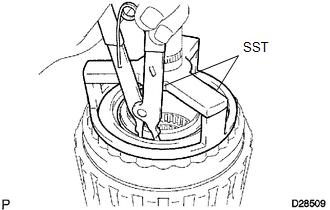
(a) Place SST on the clutch balancer and compress the return spring with a press.
SST: 09387-00070
(b) Using SST, remove the snap ring.
SST: 09350-30020
09350-07070
52. REMOVE REVERSE CLUTCH RETURN SPRING SUB-ASSEMBLY
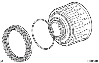
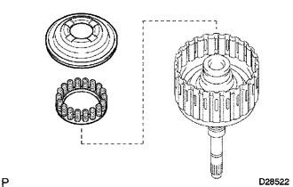
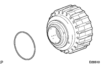
(a) Remove the reverse clutch return spring and O-ring from the reverse clutch piston.
53. INSPECT REVERSE CLUTCH RETURN SPRING SUB-ASSEMBLY
.gif)
54. REMOVE REVERSE CLUTCH PISTON SUB-ASSEMBLY
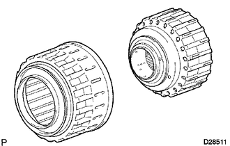
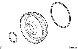
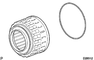
(a) Remove the reverse clutch piston sub-assembly from the clutch drum.
|
(b) Remove the O-ring from the reverse clutch piston. |
|
|
(c) Remove the O-ring from the clutch drum. |
|
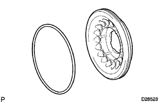
55. REMOVE DIRECT CLUTCH PISTON SUB-ASSEMBLY
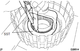
(a) Place SST on the direct clutch piston and compress the return spring with a press.
SST: 09320-89010
(b) Using SST, remove the snap ring.
SST: 09350-30020
09350-07070
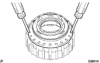
|
(c) Using 2 screwdrivers, remove the direct clutch piston sub-assembly from the clutch drum. |
|
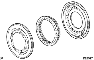
|
(d) Remove the No. 2 clutch balancer and direct clutch return spring from the direct clutch piston. |
|
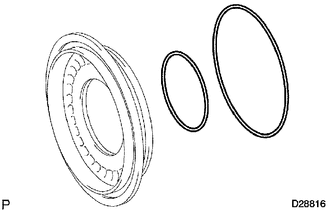
|
(e) Remove the 2 O-rings from the direct clutch piston. |
|
56. INSPECT DIRECT CLUTCH RETURN SPRING SUB-ASSEMBLY
.gif)
57. REMOVE NO. 3 BRAKE SNAP RING
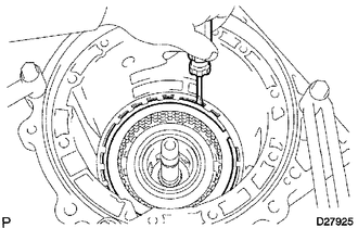
(a) Using a screwdriver, remove the No. 3 brake snap ring from the case.
58. REMOVE NO. 3 BRAKE DISC
(a) Remove the flange, 4 discs, 4 plates and cushion plate from the case.
59. INSPECT NO. 3 BRAKE DISC
.gif)
60. REMOVE 2ND BRAKE PISTON HOLE SNAP RING
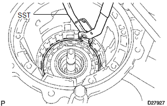
(a) Using SST, remove the snap ring.
SST: 09350-30020
09350-07060
61. REMOVE 1-WAY CLUTCH ASSEMBLY
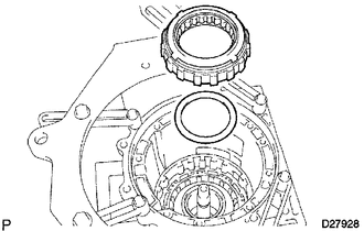
(a) Remove the 1-way clutch assembly and No. 1 planetary carrier thrust washer from the case.
62. REMOVE 2ND BRAKE CYLINDER
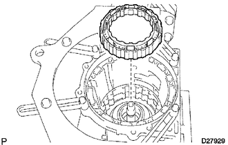
(a) Remove the 2nd brake cylinder from the case.
63. REMOVE 2ND BRAKE PISTON
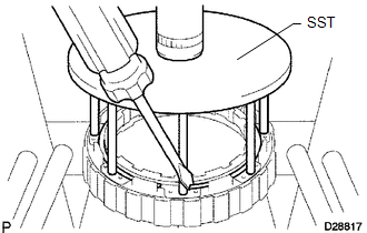
(a) Using SST and a press, compress the return spring and remove the snap ring.
SST: 09351-40010
|
(b) Hold the 2nd brake cylinder and apply compressed air (392 kPa (4.0 kgf/cm2, 57 psi)) to the 2nd brake cylinder to remove the 2nd brake piston. |
|
|
(c) Remove the 2 O-rings from the 2nd brake piston. |
|
64. INSPECT NO. 3 BRAKE PISTON RETURN SPRING SUB-ASSEMBLY
.gif)
65. REMOVE FRONT PLANETARY GEAR ASSEMBLY
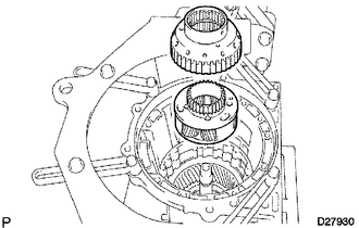
(a) Remove the 1-way clutch inner race and front planetary gear assembly from the case.
|
(b) Remove the thrust bearing race, thrust needle roller bearing and No. 2 planetary carrier thrust washer from the front planetary gear assembly. |
|
66. INSPECT FRONT PLANETARY GEAR ASSEMBLY
.gif)
67. INSPECT 1-WAY CLUTCH ASSEMBLY
.gif)
68. REMOVE FRONT PLANETARY RING GEAR
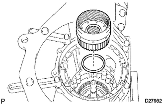
(a) Remove the front planetary ring gear and thrust needle roller bearing from the transmission case.
69. REMOVE CENTER PLANETARY RING GEAR
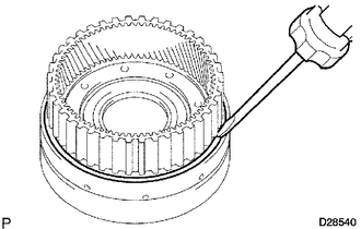
(a) Using a screwdriver, remove the snap ring.
|
(b) Remove the center planetary ring gear and front planetary ring gear flange from the front planetary ring gear. |
|
70. REMOVE NO. 1 BRAKE DISC
(a) Remove the flange, 3 discs and 3 plates from the case.
71. INSPECT NO. 1 BRAKE DISC
.gif)
72. REMOVE BRAKE PISTON RETURN SPRING SNAP RING
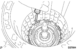
(a) Using a screwdriver, remove the brake piston return spring snap ring from the case.
73. REMOVE BRAKE PISTON RETURN SPRING SUB-ASSEMBLY
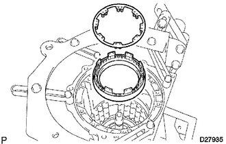
(a) Remove the brake piston return spring and No. 1 brake piston with No. 1 brake cylinder from the transmission case.
74. INSPECT BRAKE PISTON RETURN SPRING SUB-ASSEMBLY
.gif)
75. REMOVE NO. 1 BRAKE PISTON
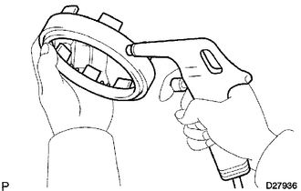
(a) Hold the No. 1 brake cylinder and apply compressed air (392 kPa (4.0 kgf/cm2, 57 psi)) to the No. 1 brake cylinder to remove the No. 1 brake piston.
HINT:
If the piston does not pop out with compressed air, lift the piston out with needle-nose pliers.
(b) Remove the 2 O-rings from the No. 1 brake piston.
76. REMOVE NO. 2 BRAKE DISC
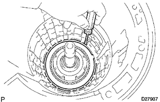
(a) Using a screwdriver, remove the snap ring from the case.
(b) Remove the flange, 3 discs, 3 plates and brake piston return spring from the case.
77. INSPECT NO. 2 BRAKE DISC
.gif)
78. INSPECT NO. 2 BRAKE PISTON RETURN SPRING SUB-ASSEMBLY
.gif)
79. REMOVE NO. 2 BRAKE PISTON
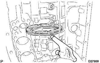
(a) Apply compressed air (392 kPa (4.0 kgf/cm2, 57 psi)) to the transmission case to remove the No. 2 brake piston.
HINT:
If the piston does not pop out with compressed air, lift the piston out with needle-nose pliers.
(b) Remove the 2 O-rings from the No. 2 brake piston.
80. REMOVE CENTER PLANETARY GEAR ASSEMBLY
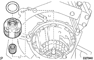
(a) Remove the thrust bearing race, center planetary gear and planetary sun gear from the case.
81. INSPECT CENTER PLANETARY GEAR ASSEMBLY
.gif)
82. REMOVE INTERMEDIATE SHAFT
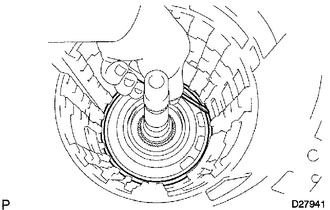
(a) Using a screwdriver, remove the snap ring from the case.
|
(b) Remove the intermediate shaft with No. 3 1-way clutch assembly from the case. |
|
83. INSPECT NO. 3 1-WAY CLUTCH ASSEMBLY
.gif)
84. REMOVE NO. 3 1-WAY CLUTCH ASSEMBLY
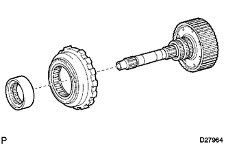
(a) Remove the No. 3 1-way clutch assembly and 1-way clutch inner race from the intermediate shaft.
85. REMOVE REAR PLANETARY RING GEAR FLANGE SUB-ASSEMBLY
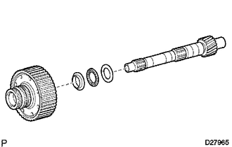
(a) Remove the planetary ring gear flange, 2 thrust bearing races and thrust needle roller bearing from the intermediate shaft.
86. INSPECT REAR PLANETARY RING GEAR FLANGE SUB-ASSEMBLY
.gif)
87. INSPECT INTERMEDIATE SHAFT
.gif)
88. REMOVE BRAKE PLATE STOPPER SPRING
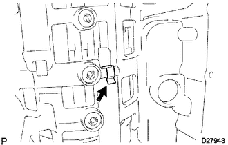
89. REMOVE NO. 4 BRAKE DISC
(a) Remove the 7 plates, 8 discs and 2 flanges from the case.
90. INSPECT NO. 4 BRAKE DISC
.gif)
91. REMOVE REAR PLANETARY GEAR ASSEMBLY
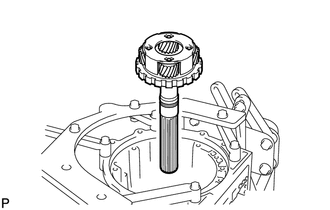
(a) Remove the rear planetary gear assembly from the case.
|
(b) Remove the 2 thrust needle roller bearings from the rear planetary gear. |
|
|
(c) Remove the thrust bearing race from the case. |
|
92. INSPECT REAR PLANETARY GEAR ASSEMBLY
.gif)
93. REMOVE 1ST AND REVERSE BRAKE RETURN SPRING SUB-ASSEMBLY
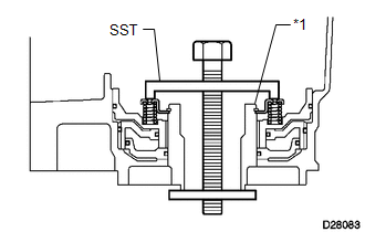
(a) Place SST on the spring retainer and compress the brake return spring.
SST: 09350-30020
09350-07050
Text in Illustration|
*1 |
Snap Ring |
(b) Using SST, remove the snap ring and brake return spring.
SST: 09350-30020
09350-07070
94. INSPECT 1ST AND REVERSE BRAKE RETURN SPRING SUB-ASSEMBLY
.gif)
95. REMOVE 1ST AND REVERSE BRAKE PISTON
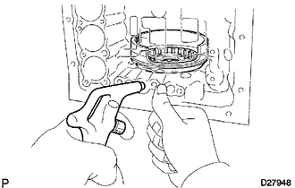
(a) Apply compressed air (392 kPa (4.0 kgf/cm2, 57 psi)) to the transmission case to remove the 1st and reverse brake piston.
HINT:
If the piston does not pop out with compressed air, lift the piston out with needle-nose pliers.
(b) Remove the O-ring from the 1st and reverse brake piston.
96. REMOVE BRAKE REACTION SLEEVE
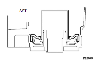
(a) Using SST, remove the reaction sleeve.
SST: 09350-30020
09350-07080
(b) Remove the 2 O-rings from the reaction sleeve.
97. REMOVE NO. 4 BRAKE PISTON
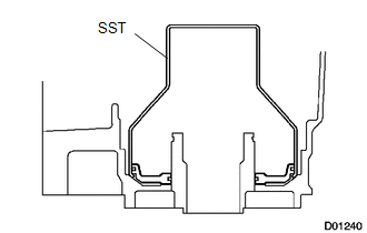
(a) Using SST, remove the brake piston.
SST: 09350-30020
09350-07090
(b) Remove the 2 O-rings from the brake piston.
 Components
COMPONENTS
ILLUSTRATION
ILLUSTRATION
ILLUSTRATION
ILLUSTRATION
ILLUSTRATION
ILLUSTRATION
ILLUSTRATION
ILLUSTRATION
ILLUSTRATION
ILLUSTRATION
ILLUSTRATION
ILLUSTRATION ...
 Inspection
INSPECTION
PROCEDURE
1. INSPECT AUTOMATIC TRANSMISSION OIL PAN SUB-ASSEMBLY
(a) Remove the magnets and use them to collect steel particles.
(b) Carefully look at the foreign matter and particles i ...
Other materials about Toyota 4Runner:
Communication Malfunction No. 1 (B2797)
DESCRIPTION
This DTC is stored when a communication error occurs between the transponder
key amplifier and transponder key ECU assembly. Some possible reasons for the communication
error are: 1) 2 or more ignition keys are positioned too close together, o ...
Lost Communication with Back Door Power Window ECU (Abnormal Power Supply) (B2327,B2328)
DESCRIPTION
DTC B2327 is stored when LIN communication between the multiplex network
door ECU (back door P/W) and back door power window regulator motor assembly
stops for 10 seconds or more.
DTC B2328 is stored when a malfunction in the LI ...
0.0069

