Toyota 4Runner: System Diagram
SYSTEM DIAGRAM
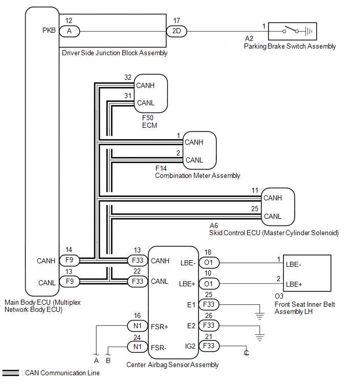
 Communication Table
|
Sender |
Receiver |
Signal |
Line |
|---|---|---|---|
|
Center airbag sensor assembly |
Main body ECU (multiplex network body ECU) |
Front seat inner belt LH buckle switch |
CAN |
|
Combination meter assembly |
|
||
|
Main body ECU (multiplex network body ECU) |
Combination meter assembly |
|
|
|
Skid control ECU (master cylinder solenoid) |
Combination meter assembly |
Vehicle speed |
|
|
ECM |
Combination meter assembly |
Shift position |
 Parts Location
PARTS LOCATION
ILLUSTRATION
ILLUSTRATION
...
 How To Proceed With Troubleshooting
CAUTION / NOTICE / HINT
HINT:
Use the following procedures to troubleshoot the seat belt warning system.
*: Use the Techstream.
PROCEDURE
1.
VEHICLE BRO ...
Other materials about Toyota 4Runner:
Types of child restraints
Child restraint systems are classified into the following 3 types according
to the age and size of the child:
Rear facing — Infant seat/convertible seat
Forward facing — Convertible seat
Booster seat
Selecting an appropriate child restraint sys ...
Satellite Radio Broadcast cannot be Selected or After Selecting Broadcast, Broadcast
cannot be Added into Memory
CAUTION / NOTICE / HINT
NOTICE:
Some satellite radio broadcasts require payment. A contract must be
made between a satellite radio company and the user. If the contract expires,
it will not be possible to listen to the broadcast.
PROCE ...

0.014