Toyota 4Runner: Disposal
DISPOSAL
CAUTION / NOTICE / HINT
CAUTION:
Before performing pre-disposal deployment of any SRS part, review and closely follow all applicable environmental and hazardous material regulations. Pre-disposal deployment may be considered hazardous material treatment.
PROCEDURE
1. PRECAUTION
HINT:
When scrapping a vehicle equipped with the SRS or disposing of the steering pad, be sure to deploy the airbag first in accordance with the procedure described below. If any abnormality occurs with the airbag deployment, contact the SERVICE DEPT. of TOYOTA MOTOR SALES, U.S.A., INC.
CAUTION:
- Never dispose of a steering pad that has an unactivated airbag.
- The airbag produces an exploding sound when it is deployed, so perform the operation outdoors and where it will not create a nuisance to nearby residents.
- When deploying the airbag, always use the specified SST (SRS Airbag Deployment Tool). Perform the operation in a place away from electrical noise.
- When deploying the airbag, perform the operation at least 10 m (32.8 ft.) away from the steering pad.
- The steering pad becomes extremely hot when the airbag is deployed, so do not touch it for at least 30 minutes after deployment.
- Use gloves and safety glasses when handling a steering pad with a deployed airbag.
- Do not apply water, etc. to a steering pad with a deployed airbag.
- Always wash your hands with water after completing the operation.
- An airbag or pretensioner may be activated by static electricity. To prevent this, be sure to touch a metal surface with bare hands to discharge static electricity before performing this procedure.
2. DISPOSE OF STEERING PAD (WHEN INSTALLED IN VEHICLE)
HINT:
Prepare a battery as the power source to deploy the airbag.
|
(a) Check the function of SST (See page
|
|
.png)
(b) Read the precaution (See page .gif) ).
).
(c) Disconnect the cable from the negative (-) battery terminal.
CAUTION:
Wait at least 90 seconds after disconnecting the cable from the negative (-) battery terminal to disable the SRS system.
NOTICE:
When disconnecting the cable, some systems need to be initialized after the cable
is reconnected (See page ).
|
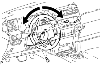
(d) Remove the steering column cover lower. (1) While turning the steering wheel to the right and left, remove the 3 screws and steering column cover lower. |
|
(e) Install SST.
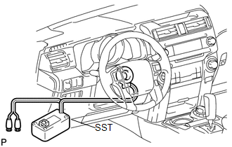
SST: 09082-00700
CAUTION:
Check that there is no looseness in the steering wheel assembly and steering pad.
(1) Disconnect the airbag connector (yellow colored) from the spiral cable with steering sensor.
NOTICE:
When handling the airbag connector, take care not to damage the airbag wire harness.
(2) Connect SST connector to the airbag connector of the spiral cable with steering sensor.
SST: 09082-00780
NOTICE:
To avoid damaging SST connector and wire harness, do not lock the secondary lock of the twin lock.
|
(3) Move SST at least 10 m (32.8 ft.) away from the vehicle front side window. Text in Illustration
|
|
.png)
(4) Maintaining enough clearance for SST wire harness in the front side window, close all doors and windows of the vehicle.
NOTICE:
Take care not to damage SST wire harness.
(5) Connect the red clip of SST to the positive (+) battery terminal and the black clip of SST to the negative (-) battery terminal.
(f) Deploy the airbag.
(1) Check that no one is inside the vehicle or within a 10 m (32.8 ft.) radius of the vehicle.
(2) Press SST activation switch to deploy the airbag.
CAUTION:
- When deploying the airbag, make sure that no one is near the vehicle.
- The steering pad becomes extremely hot when the airbag is deployed, so do not touch it for at least 30 minutes after deployment.
- Use gloves and safety glasses when handling a steering pad with a deployed airbag.
- Do not apply water to a steering pad with a deployed airbag.
- Always wash your hands with water after completing the operation.
HINT:
The airbag is deployed as the LED of SST activation switch comes on.
3. DISPOSE OF STEERING PAD (WHEN NOT INSTALLED IN VEHICLE)
CAUTION:
Be sure to follow the procedure detailed below when deploying the airbag.
HINT:
Prepare a battery as the power source to deploy the airbag.
(a) Check the function of SST.
SST: 09082-00700
|
(b) Remove the steering pad (See page CAUTION:
|
|
(c) Using a service-purpose wire harness for the vehicle, tie down the steering pad to a disc wheel.
.png) Text in Illustration
Text in Illustration
|
*a |
Wire Harness Diameter |
|
*b |
Stripped Wire Harness Section |
Cross-sectional area of stripped wire harness section:
1.25 mm2 (0.00192 in.2)
CAUTION:
If the wire harness is too thin or an alternative object is used to tie down the steering pad, it may be snapped by the shock when the airbag is deployed. Always use a wire harness for vehicle use with a cross-sectional area of at least 1.25 mm2 (0.00192 in.2).
HINT:
To calculate the cross-sectional area of the stripped wire harness section: Area = 3.14 x (Diameter)2 / 4
|
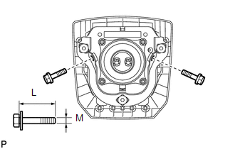
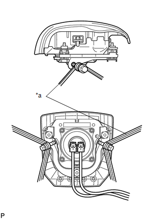
(1) Install 2 bolts with washers into the 2 bolt holes on the steering pad. Bolt: L: 35.0 mm (1.38 in.) M: 6.0 mm (0.236 in.) Pitch: 1.0 mm (0.0393 in.) NOTICE:
|
|
|
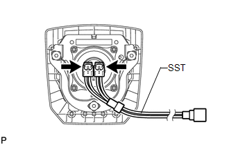
(2) After connecting SST to each other, connect them to the steering pad. SST: 09082-00820 |
|
|
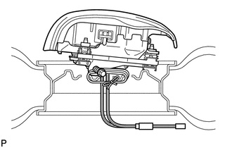
(3) Wind 3 wire harnesses at least 2 times each around the bolts installed on the left and right sides of the steering pad. Text in Illustration
CAUTION:
|
|
|
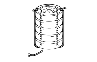
(4) Face the airbag deployment side of the steering pad upward. Separately tie the left and right sides of the steering pad to a disc wheel through the hub nut holes. Position SST connector so that it hangs downward through the hub hole of the disc wheel. CAUTION:
NOTICE: As the disc wheel may be damaged by the airbag deployment, use a disc wheel that you are planning to throw away. |
|
(d) Install SST.
CAUTION:
Place the disc wheel on level ground.
(1) Connect SST connector.
SST: 09082-00700
NOTICE:
To avoid damaging SST connector and wire harness, do not lock the secondary lock of the twin lock. Also, secure some slack for SST wire harness inside the disc wheel.
|
(2) Move SST at least 10 m (32.8 ft.) away from the steering pad tied down to the disc wheel. Text in Illustration
|
|
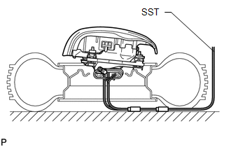
(e) Cover the steering pad with a cardboard box or tires.
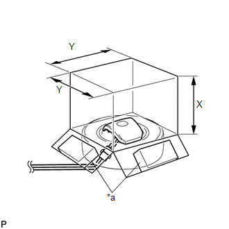 Text in Illustration
|
*a |
Weight |
(1) Covering method using a cardboard box: Cover the steering pad with the cardboard box and place weights on the cardboard box in 4 places with a total of at least 190 N (19 kgf, 41.8 lbf).
Cardboard box size:
Must exceed the following dimensions
X: 460 mm (18.1 in.)
Y: 650 mm (25.6 in.)
NOTICE:
- When dimension Y of the cardboard box exceeds the diameter of the tire with disc wheel which the steering pad is tied to, X should be the following size. X = 460 mm (18.1 in.) + width of tire
- If a cardboard box which is smaller than the specified size is used, the cardboard box will be damaged by the shock from the airbag deployment.
|
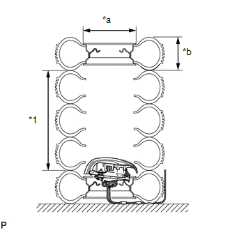
(2) Covering method using tires: Place at least 3 tires without disc wheels on the tire with disc wheel which the steering pad is tied to. Place another tire with disc wheel on them. Text in Illustration
Tire size: Must exceed the following dimensions Width: 185 mm (7.28 in.) Inner diameter: 360 mm (14.2 in.) CAUTION: Do not use tires with disc wheels except on the top and bottom. NOTICE:
|
|
|
(3) Tie the tires together with 2 wire harnesses. CAUTION: Make sure that the wire harnesses are tight. Looseness in the wire harnesses results in the tires coming free due to the shock when the airbag is deployed. |
|
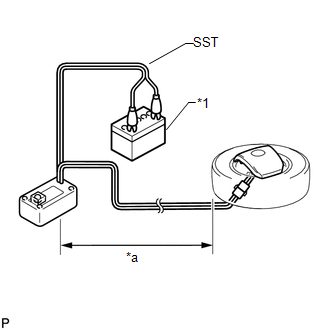
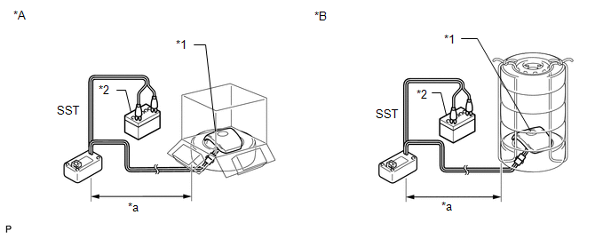
(f) Deploy the airbag.
 Text in Illustration
|
*A |
Using Cardboard Box |
|
*B |
Using Tires |
|
*1 |
Steering Pad |
|
*2 |
Battery |
|
*a |
10 m or more |
(1) Connect the red clip of SST to the positive (+) battery terminal and the black clip of SST to the battery negative (-) battery terminal.
(2) Check that no one is within a 10 m (32.8 ft.) radius of the disc wheel which the steering pad is tied to.
(3) Press SST activation switch to deploy the airbag.
CAUTION:
When deploying the airbag, make sure that no one is near the tire.
HINT:
The airbag is deployed as the LED of SST activation switch comes on.
|
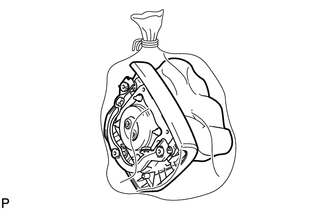
(g) Dispose of the steering pad. CAUTION:
(1) Remove the steering pad from the disc wheel. (2) Place the steering pad in a plastic bag, tie it tightly and dispose of it in the same way as other general parts. |
|
 Removal
REMOVAL
PROCEDURE
1. DISCONNECT CABLE FROM NEGATIVE BATTERY TERMINAL
CAUTION:
Wait at least 90 seconds after disconnecting the cable from the negative (-)
battery terminal to disable the SRS sys ...
 Installation
INSTALLATION
PROCEDURE
1. INSTALL STEERING PAD
(a) Support the steering pad with one hand.
(b) Connect the 2 connectors to the steering pad.
N ...
Other materials about Toyota 4Runner:
Problem Symptoms Table
PROBLEM SYMPTOMS TABLE
HINT:
Use the table below to help determine the cause of problem symptoms.
If multiple suspected areas are listed, the potential causes of the symptoms
are listed in order of probability in the "Suspected Area" ...
System Description
SYSTEM DESCRIPTION
1. SYSTEM DESCRIPTION
(a) The Electronic Controlled Automatic Transmission (ECT) is an automatic transmission
that electronically controls shift timing using the Engine Control Module (ECM).
The ECM detects electrical signals that indi ...

0.0079