Toyota 4Runner: Installation
INSTALLATION
PROCEDURE
1. INSTALL STEERING PAD
|
(a) Support the steering pad with one hand. |
|
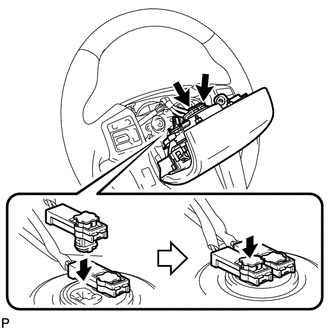
(b) Connect the 2 connectors to the steering pad.
NOTICE:
When handling the airbag connector, take care not to damage the airbag wire harness.
(c) Connect the horn connector.
(d) Confirm that the groove along the circumference of the "TORX" screw is attached to the screw case and place the steering pad onto the steering wheel.
(e) Using a T30 "TORX" socket wrench, tighten the 2 screws.
Torque:
8.8 N·m {90 kgf·cm, 78 in·lbf}
2. INSTALL LOWER NO. 3 STEERING WHEEL COVER
(a) Attach the 2 claws to install the cover.
3. INSTALL LOWER NO. 2 STEERING WHEEL COVER
|
(a) Attach the 2 claws to install the cover. Text in Illustration
|
|
.png)
4. CONNECT CABLE TO NEGATIVE BATTERY TERMINAL
NOTICE:
When disconnecting the cable, some systems need to be initialized after the cable
is reconnected (See page .gif) ).
).
5. INSPECT STEERING PAD
(a) With the steering pad installed on the vehicle, perform a visual check. If there are any defects as mentioned below, replace the steering pad with a new one:
Cuts, minute cracks or marked discoloration on the steering pad top surface or in the grooved portion.
(b) Make sure that the horn sounds.
If the horn does not sound, inspect the horn system.
6. CHECK SRS WARNING LIGHT
(a) Check the SRS warning light (See page ).
 Disposal
DISPOSAL
CAUTION / NOTICE / HINT
CAUTION:
Before performing pre-disposal deployment of any SRS part, review and closely
follow all applicable environmental and hazardous material regulations. Pre ...

Other materials about Toyota 4Runner:
Inspection
INSPECTION
PROCEDURE
1. INSPECT DOOR CONTROL TRANSMITTER MODULE
(a) Inspect the operation of the transmitter.
(1) Remove the battery (lithium battery) from the transmitter (See page
).
(2) Install a new or normal battery (lithium battery).
...
Initialization
INITIALIZATION
1. PROCEDURES NECESSARY WHEN CABLE IS DISCONNECTED/RECONNECTED TO BATTERY TERMINAL
Procedures Necessary when Cable is Disconnected/Reconnected to Battery Terminal
Necessary Procedure
Effect or Inoperative Function when N ...

0.027