Toyota 4Runner: Downhill Assist Control Indicator Light does not Come ON
DESCRIPTION
Even if the downhill assist control switch is pressed, the downhill assist control indicator light blinks and downhill assist control does not activate under the following conditions:
- The transfer is in H4.
- The brake system is malfunctioning.
- The temperature of the hydraulic brake booster increases and downhill assist control is temporarily canceled.
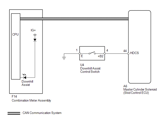
WIRING DIAGRAM
CAUTION / NOTICE / HINT
NOTICE:
When replacing the master cylinder solenoid, perform calibration (See page
.gif) ).
).
PROCEDURE
|
1. |
CHECK CAN COMMUNICATION LINE |
(a) Turn the ignition switch off.
(b) Connect the Techstream to the DLC3.
(c) Turn the ignition switch to ON.
(d) Turn the Techstream on.
(e) Select CAN Bus Check from the System Selection Menu screen and follow the
prompts on the screen to inspect the CAN bus (See page
).
OK:
CAN Bus Check indicates no malfunctions in CAN communication.
| NG | .gif) |
GO TO CAN COMMUNICATION SYSTEM (HOW TO PROCEED WITH TROUBLESHOOTING) |
|
.gif)
|
2. |
CHECK FOR DTC |
(a) Check for DTCs (See page ).
Result
|
Result |
Proceed to |
|---|---|
|
DTC is not output |
A |
|
DTC is output |
B |
| B | |
REPAIR CIRCUITS INDICATED BY OUTPUT DTCS |
|
|
3. |
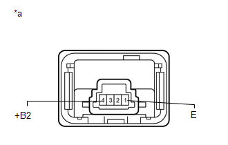
INSPECT DOWNHILL ASSIST CONTROL SWITCH |
(a) Remove the downhill assist control switch (See page
).
|
(b) Measure the resistance according to the value(s) in the table below. Standard Resistance:
|
|
| NG | |
REPLACE DOWNHILL ASSIST CONTROL SWITCH |
|
|
4. |
CHECK HARNESS AND CONNECTOR (SKID CONTROL ECU HDCS CIRCUIT) |
(a) Disconnect the A6 skid control ECU connector.
(b) Disconnect the U4 downhill assist control switch connector.
(c) Measure the resistance according to the value(s) in the table below.
Standard Resistance:
|
Tester Connection |
Condition |
Specified Condition |
|---|---|---|
|
A6-44 (HDCS) - U4-4 (+B2) |
Always |
Below 1 Ω |
|
A6-44 (HDCS) - Body ground |
Always |
10 kΩ or higher |
|
U4-1 (E) - Body ground |
Always |
Below 1 Ω |
| NG | |
REPAIR OR REPLACE HARNESS OR CONNECTOR |
|
|
5. |
READ VALUE USING TECHSTREAM (DOWNHILL ASSIST CONTROL LIGHT) |
(a) Turn the ignition switch off.
(b) Connect the Techstream to the DLC3.
(c) Turn the ignition switch to ON.
(d) Turn the Techstream on.
(e) Enter the following menus: Chassis / ABS/VSC/TRAC / Data List.
ABS/VSC/TRAC|
Tester Display |
Measurement Item/Range |
Normal Condition |
Diagnostic Note |
|---|---|---|---|
|
Downhill Assist Control Light |
Downhill assist control indicator light/ ON or OFF |
ON: Indicator light on OFF: Indicator light off |
- |
(f) When performing the Downhill Assist Control Light Active Test, check Downhill
Assist Control Light in the Data List (See page
).
|
Tester Display |
Test Part |
Control Range |
Diagnostic Note |
|---|---|---|---|
|
Downhill Assist Control Light |
Downhill assist control indicator light |
Indicator light ON/OFF |
Observe the combination meter. |
|
Result |
Proceed to |
|
|---|---|---|
|
Data List Display |
Data List Display when Performing Active Test ON/OFF Operation |
|
|
ON |
Does not change between ON and OFF |
A |
|
Changes between ON and OFF |
B |
|
|
OFF |
Does not change between ON and OFF |
A |
|
Changes between ON and OFF |
B |
|
| A | |
REPLACE MASTER CYLINDER SOLENOID |
| B | |
GO TO METER / GAUGE SYSTEM (HOW TO PROCEED WITH TROUBLESHOOTING) |
 Downhill Assist Control Indicator Light Remains ON
DESCRIPTION
When the downhill assist control switch is turned on, the downhill assist control
function is available and the downhill assist control indicator light illuminates.
WIRING DIAGRAM
Ref ...
 AUTO LSD Indicator Light Remains ON
DESCRIPTION
During normal mode, pressing the VSC OFF switch for a short amount of time changes
vehicle to AUTO LSD mode.
WIRING DIAGRAM
CAUTION / NOTICE / HINT
NOTICE:
When replacing the mast ...
Other materials about Toyota 4Runner:
If the vehicle battery is discharged
The following procedures may be used to start the engine if the vehicle's
battery is discharged.
You can also call your Toyota dealer or a qualified repair shop.
If you have a set of jumper (or booster) cables and a second vehicle with a
12-volt batt ...
Terminals Of Ecu
TERMINALS OF ECU
1. CHECK TIRE PRESSURE WARNING ECU
HINT:
Inspect the connector from the back side.
(a) Disconnect the F7 ECU connector.
(b) Measure the voltage according to the value(s) in the table below.
Terminal No. (Symbol)
W ...

0.0073