Toyota 4Runner: AUTO LSD Indicator Light Remains ON
DESCRIPTION
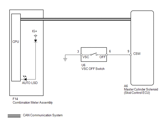
During normal mode, pressing the VSC OFF switch for a short amount of time changes vehicle to AUTO LSD mode.
WIRING DIAGRAM
CAUTION / NOTICE / HINT
NOTICE:
When replacing the master cylinder solenoid, perform calibration (See page
.gif) ).
).
PROCEDURE
|
1. |
CHECK CAN COMMUNICATION LINE |
(a) Turn the ignition switch off.
(b) Connect the Techstream to the DLC3.
(c) Turn the ignition switch to ON.
(d) Turn the Techstream on.
(e) Select CAN Bus Check from the System Selection Menu screen and follow the
prompts on the screen to inspect the CAN bus (See page
).
OK:
CAN Bus Check indicates no malfunctions in CAN communication.
| NG | .gif) |
GO TO CAN COMMUNICATION SYSTEM (HOW TO PROCEED WITH TROUBLESHOOTING) |
|
.gif)
|
2. |
INSPECT VSC OFF SWITCH |
| NG | |
REPLACE VSC OFF SWITCH |
|
|
3. |
CHECK HARNESS AND CONNECTOR (SKID CONTROL ECU - VSC OFF SWITCH) |
| NG | |
REPAIR OR REPLACE HARNESS OR CONNECTOR |
|
|
4. |
READ VALUE USING TECHSTREAM (AUTO LSD INDICATOR LIGHT) |
(a) Turn the ignition switch off.
(b) Connect the Techstream to the DLC3.
(c) Turn the ignition switch to ON.
(d) Turn the Techstream on.
(e) Enter the following menus: Chassis / ABS/VSC/TRAC / Data List.
ABS/VSC/TRAC|
Tester Display |
Measurement Item/Range |
Normal Condition |
Diagnostic Note |
|---|---|---|---|
|
Auto LSD Indicator Light |
Auto LSD indicator light/ ON or OFF |
ON: Indicator light on OFF: Indicator light off |
- |
(f) When performing the Auto LSD Indicator Light Active Test, check Auto LSD
Indicator Light in the Data List (See page ).
ABS/VSC/TRAC
|
Tester Display |
Test Part |
Control Range |
Diagnostic Note |
|---|---|---|---|
|
Auto LSD Indicator Light |
Auto LSD indicator light |
Indicator light ON/OFF |
Observe the combination meter. |
|
Result |
Proceed to |
|
|---|---|---|
|
Data List Display |
Data List Display when Performing Active Test ON/OFF Operation |
|
|
ON |
Does not change between ON and OFF |
A |
|
Changes between ON and OFF |
B |
|
|
OFF |
Does not change between ON and OFF |
A |
|
Changes between ON and OFF |
B |
|
| A | |
REPLACE MASTER CYLINDER SOLENOID |
| B | |
GO TO METER / GAUGE SYSTEM (HOW TO PROCEED WITH TROUBLESHOOTING) |
 Downhill Assist Control Indicator Light does not Come ON
DESCRIPTION
Even if the downhill assist control switch is pressed, the downhill assist control
indicator light blinks and downhill assist control does not activate under the following
conditions: ...
 A-TRAC Indicator Light Remains ON
DESCRIPTION
This is the A-TRAC main switch circuit. When the A-TRAC switch is turned on with
the transfer in L4, the A-TRAC function is available and the A-TRAC indicator light
illuminates.
WIRI ...
Other materials about Toyota 4Runner:
How To Proceed With Troubleshooting
CAUTION / NOTICE / HINT
HINT:
Use these procedures to troubleshoot the meter/gauge system.
*: Use the Techstream.
PROCEDURE
1.
VEHICLE BROUGHT TO WORKSHOP
NEXT
...
Terminals Of Ecu
TERMINALS OF ECU
1. CHECK POWER MANAGEMENT CONTROL ECU
(a) Disconnect the F80 power management control ECU connector.
(b) Measure the voltage and resistance according to the value(s) in the table
below.
Terminal No. (Symbol)
Wirin ...

0.0077