Toyota 4Runner: Driver Side Power Window does not Operate with Power Window Master Switch
DESCRIPTION
- If the manual up/down function does not operate, there may be a malfunction in the multiplex network master switch, power window regulator motor, harness or connector.
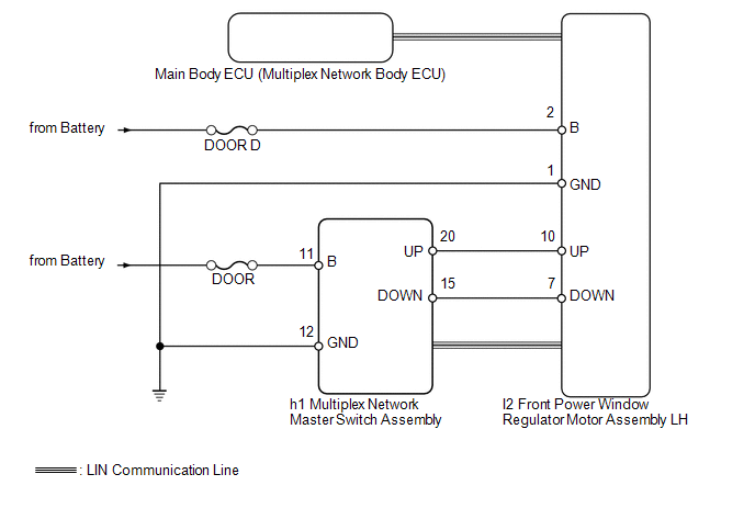
WIRING DIAGRAM
CAUTION / NOTICE / HINT
NOTICE:
Inspect the fuses for circuits related to this system before performing the following inspection procedure.
HINT:
Since the power window control system has functions that use LIN communication, first confirm that there is no malfunction in the communication system by inspecting the LIN communication functions in accordance with the "How to Proceed with Troubleshooting" procedures. Then, conduct the following inspection procedure.
PROCEDURE
|
1. |
CHECK FOR DTC (B2312) |
(a) Check if DTC B2312 is output (See page .gif) ).
).
OK:
DTC B2312 is not output.
| NG | .gif) |
GO TO DTC B2312 |
|
.gif)
|
2. |
READ VALUE USING TECHSTREAM (MULTIPLEX NETWORK MASTER SWITCH ASSEMBLY) |
(a) Use the Data List to check if the multiplex network master switch is functioning
properly (See page ).
D-Door Motor
|
Tester Display |
Measurement Item/Range |
Normal Condition |
Diagnostic Note |
|---|---|---|---|
|
D Door P/W Up SW |
Driver side power window manual up signal / ON or OFF |
ON: Driver side power window manual up switch operated OFF: Driver side power window switch not operated |
- |
|
D Door P/W Down SW |
Driver side power window manual down signal / ON or OFF |
ON: Driver side power window manual down switch operated OFF: Driver side power window switch not operated |
- |
OK:
On tester screen, each item changes between ON and OFF according to above chart.
| NG | |
GO TO STEP 4 |
|
|
3. |
PERFORM ACTIVE TEST USING TECHSTREAM (POWER WINDOW) |
(a) Select the Active Test, use the Techstream to generate a control command,
and then check that power window regulator motor operates (See page
).
D-Door Motor
|
Tester Display |
Test Part |
Control Range |
Diagnostic Note |
|---|---|---|---|
|
Power Window |
Driver side power window |
OFF/UP/DOWN |
- |
OK:
The power window regulator motor operates normally.
| OK | |
REPLACE MAIN BODY ECU (MULTIPLEX NETWORK BODY ECU) |
| NG | |
REPLACE FRONT POWER WINDOW REGULATOR MOTOR ASSEMBLY LH |
|
4. |
CHECK HARNESS AND CONNECTOR (MULTIPLEX NETWORK MASTER SWITCH ASSEMBLY - BATTERY AND BODY GROUND) |
|
(a) Disconnect the h1 multiplex network master switch connector. |
|
(b) Measure the voltage and resistance according to the value(s) in the table below.
Standard Voltage:
|
Tester Connection |
Condition |
Specified Condition |
|---|---|---|
|
h1-11 (B) - Body ground |
Always |
11 to 14 V |
Standard Resistance:
|
Tester Connection |
Condition |
Specified Condition |
|---|---|---|
|
h1-12 (GND) - Body ground |
Always |
Below 1 Ω |
|
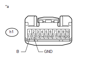
*a |
Front view of wire harness connector (to Multiplex Network Master Switch Assembly) |
| NG | |
REPAIR OR REPLACE HARNESS OR CONNECTOR |
|
|
5. |
CHECK HARNESS AND CONNECTOR (FRONT POWER WINDOW REGULATOR MOTOR ASSEMBLY LH - BATTERY AND BODY GROUND) |
|
(a) Disconnect the I2 power window regulator motor connector. |
|
(b) Measure the voltage and resistance according to the value(s) in the table below.
Standard Voltage:
|
Tester Connection |
Condition |
Specified Condition |
|---|---|---|
|
I2-2 (B) - Body ground |
Always |
11 to 14 V |
Standard Resistance:
|
Tester Connection |
Condition |
Specified Condition |
|---|---|---|
|
I2-1 (GND) - Body ground |
Always |
Below 1 Ω |
|
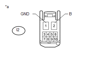
*a |
Front view of wire harness connector (to Front Power Window Regulator Motor Assembly LH) |
| NG | |
REPAIR OR REPLACE HARNESS OR CONNECTOR |
|
|
6. |
CHECK HARNESS AND CONNECTOR (MULTIPLEX NETWORK MASTER SWITCH ASSEMBLY - FRONT POWER WINDOW REGULATOR MOTOR ASSEMBLY LH) |
(a) Disconnect the h1 multiplex network master switch connector.
(b) Disconnect the I2 power window regulator motor connector.
(c) Measure the resistance according to the value(s) in the table below.
Standard Resistance:
|
Tester Connection |
Condition |
Specified Condition |
|---|---|---|
|
h1-20 (UP) - I2-10 (UP) |
Always |
Below 1 Ω |
|
h1-15 (DOWN) - I2-7 (DOWN) |
Always |
Below 1 Ω |
|
h1-20 (UP) - Body ground |
Always |
10 kΩ or higher |
|
h1-15 (DOWN) - Body ground |
Always |
10 kΩ or higher |
| NG | |
REPAIR OR REPLACE HARNESS OR CONNECTOR |
|
|
7. |
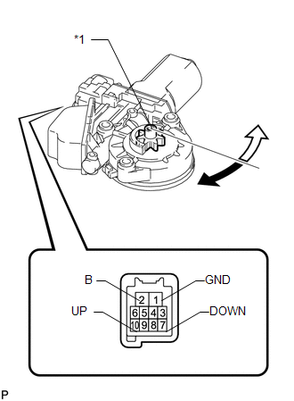
INSPECT FRONT POWER WINDOW REGULATOR MOTOR ASSEMBLY LH |
(a) Remove the front power window regulator motor LH (See page
).
(b) Check that the window regulator motor moves smoothly as follows.
NOTICE:
- Do not apply positive (+) battery voltage to any terminal other than terminal 2 (B) to avoid damaging the pulse sensor inside the motor.
- Reset the power window regulator motor (initialize the pulse sensor) after installing the power window regulator motor to the door.
OK:
|
Measurement Condition |
Specified Condition |
|---|---|
|
Motor gear rotates clockwise (Up) |
|
Motor gear rotates counterclockwise (Down) |
|
*1 |
Motor Gear |
.png) |
Clockwise |
.png) |
Counterclockwise |
| OK | |
REPLACE MULTIPLEX NETWORK MASTER SWITCH ASSEMBLY |
| NG | |
REPLACE FRONT POWER WINDOW REGULATOR MOTOR ASSEMBLY LH |
 Manual Up / Down Function does not Operate on Back Door Only
DESCRIPTION
If the back door power window does not operate, the retract switch in the rear
wiper motor, the back door power window regulator motor or the wire harness may
be abnormal.
WIRING DIA ...
 Front Passenger Side Power Window does not Operate with Front Passenger Side
Power Window Switch
Front Passenger Side Power Window does not Operate with Front Passenger Side
Power Window Switch
DESCRIPTION
If the manual up/down function does not operate, there may be a malfunction
in the power window regulator switch, front power window regulator motor,
harness or connector. ...
Other materials about Toyota 4Runner:
Installation
INSTALLATION
CAUTION / NOTICE / HINT
HINT:
A bolt without a torque specification is shown in the standard bolt chart (See
page ).
PROCEDURE
1. INSTALL POWER STEERING ECU ASSEMBLY
(a) Attach the 2 claws to install the power steering ECU assembly.
2. I ...
No Sound can be Heard from Speakers
PROCEDURE
1.
CHECK AUDIO SETTINGS
(a) In sound output setting mode, set volume, fader and balance to the initial
values and check that the sound is normal.
OK:
Audio system returns to normal.
HINT:
Sound quality adjustm ...

0.0077