Toyota 4Runner: Manual Up / Down Function does not Operate on Back Door Only
DESCRIPTION
If the back door power window does not operate, the retract switch in the rear wiper motor, the back door power window regulator motor or the wire harness may be abnormal.
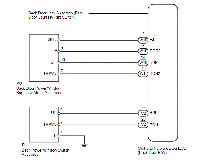
WIRING DIAGRAM
PROCEDURE
|
1. |
SYSTEM CHECK |
(a) Check the back door switch.
|
Result |
Proceed to |
|---|---|
|
All back door switches do not operate |
A |
|
Back door power window regulator switch does not operate |
B |
|
Tail gate control switch does not operate |
C |
|
Back door control switch does not operate |
D |
| B | .gif) |
GO TO STEP 8 |
| C | |
GO TO POWER DOOR LOCK CONTROL SYSTEM |
| D | |
GO TO SMART KEY SYSTEM (for Entry Function) |
|
.gif)
|
2. |
CHECK LIGHTING SYSTEM (BACK DOOR COURTESY LIGHT SWITCH) |
(a) Use the Data List to check if the back door courtesy light switch is functioning
properly (See page .gif) ).
).
Back Door P/W
|
Tester Display |
Measurement Item/Range |
Normal Condition |
Diagnostic Note |
|---|---|---|---|
|
Back Door Courtesy Switch |
Back door courtesy light switch signal / ON or OFF |
ON: Back door open OFF: Back door closed |
- |
OK:
On tester screen, item changes between ON and OFF according to above chart.
| NG | |
GO TO LIGHTING SYSTEM |
|
|
3. |
CHECK REAR WIPER SYSTEM (REAR WIPER POSITION) |
(a) Use the Data List to check if the rear wiper is functioning properly (See
page ).
Back Door P/W
|
Tester Display |
Measurement Item/Range |
Normal Condition |
Diagnostic Note |
|---|---|---|---|
|
Wiper Retracted Position |
Rear wiper reverse position switch signal / ON or OFF |
ON: Rear wiper reverse position switch is in ON position OFF: Rear wiper reverse position switch is in OFF position |
- |
|
Wiper Reverse Position |
Rear wiper reverse position switch signal / ON or OFF |
ON: Rear wiper in reverse position OFF: Rear wiper in other position |
- |
OK:
On tester screen, each item changes between ON and OFF according to above chart.
| NG | |
GO TO REAR WIPER SYSTEM |
|
|
4. |
CHECK FOR DTC (B2312) |
(a) Check if DTC B2312 is output (See page ).
OK:
DTC B2312 is not output.
| NG | |
GO TO DTC B2312 |
|
|
5. |
PERFORM ACTIVE TEST USING TECHSTREAM (BACK DOOR POWER WINDOW) |
(a) Select the Active Test, use the Techstream to generate a control command,
and then check that the door window regulator operates (See page
).
Back Door P/W
|
Tester Display |
Test Part |
Control Range |
Diagnostic Note |
|---|---|---|---|
|
Back Door power Window |
Back door power window |
OFF/UP/DOWN |
- |
OK:
The power window regulator operates normally.
| OK | |
REPLACE MULTIPLEX NETWORK DOOR ECU (BACK DOOR P/W) |
|
|
6. |
INSPECT BACK DOOR POWER WINDOW REGULATOR MOTOR ASSEMBLY |
|
(a) Remove the back door power window regulator motor (See page
|
|
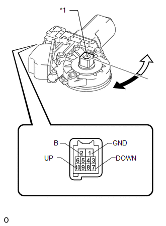
(b) Check that the back door power window regulator motor moves smoothly as follows.
NOTICE:
- Do not apply positive (+) battery voltage to any terminal other than terminal 2 (B) to avoid damaging the pulse sensor inside the motor.
- Reset the door window regulator (initialize the pulse sensor) after installing the door window regulator to the door.
|
Measurement Condition |
Specified Condition |
|---|---|
|
Motor gear rotates clockwise (Up) |
|
Motor gear rotates counterclockwise (Down) |
|
*1 |
Motor Gear |
.png) |
Clockwise |
.png) |
Counterclockwise |
| NG | |
REPLACE BACK DOOR POWER WINDOW REGULATOR MOTOR ASSEMBLY |
|
|
7. |
CHECK HARNESS AND CONNECTOR (BACK DOOR POWER WINDOW REGULATOR MOTOR ASSEMBLY - MULTIPLEX NETWORK DOOR ECU) |
(a) Disconnect the W9 back door power window regulator motor connector.
(b) Disconnect the W10 multiplex network door ECU connector.
(c) Measure the resistance according to the value(s) in the table below.
Standard Resistance:
|
Tester Connection |
Condition |
Specified Condition |
|---|---|---|
|
W9-10 (UP) - W10-14 (BUP2) |
Always |
Below 1 Ω |
|
W9-7 (DOWN) - W10-13 (BDN2) |
Always |
Below 1 Ω |
|
W9-10 (UP) - Body ground |
Always |
10 kΩ or higher |
|
W9-7 (DOWN) - Body ground |
Always |
10 kΩ or higher |
| OK | |
REPLACE MULTIPLEX NETWORK DOOR ECU (BACK DOOR P/W) |
| NG | |
REPAIR OR REPLACE HARNESS OR CONNECTOR |
|
8. |
INSPECT BACK DOOR POWER WINDOW REGULATOR SWITCH ASSEMBLY |
(a) Remove the back door power window regulator switch (See page
).
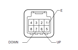
(b) Measure the resistance according to the value(s) in the table below.
Standard Resistance:
|
Tester Connection |
Switch Condition |
Specified Condition |
|---|---|---|
|
6 (UP) - 1 (E) |
Manual up operation |
Below 1 Ω |
|
7 (DOWN) - 1 (E) |
Manual down operation |
Below 1 Ω |
|
6 (UP) - 1 (E) |
Not operated |
10 kΩ or higher |
|
7 (DOWN) - 1 (E) |
Not operated |
10 kΩ or higher |
| NG | |
REPLACE BACK DOOR POWER WINDOW REGULATOR SWITCH ASSEMBLY |
|
|
9. |
CHECK HARNESS AND CONNECTOR (BACK DOOR POWER WINDOW REGULATOR SWITCH ASSEMBLY - MULTIPLEX NETWORK DOOR ECU) |
(a) Disconnect the f1 back door power window regulator switch connector.
(b) Disconnect the V2 multiplex network door ECU connector.
(c) Measure the resistance according to the value(s) in the table below.
Standard Resistance:
|
Tester Connection |
Condition |
Specified Condition |
|---|---|---|
|
f1-6 (UP) - V2-22 (BUP) |
Always |
Below 1 Ω |
|
f1-7 (DOWN) - V2-23 (BDN) |
Always |
Below 1 Ω |
|
f1-1 (E) - Body ground |
Always |
Below 1 Ω |
|
f1-6 (UP) - Body ground |
Always |
10 kΩ or higher |
|
f1-7 (DOWN) - Body ground |
Always |
10 kΩ or higher |
| OK | |
REPLACE MULTIPLEX NETWORK DOOR ECU (BACK DOOR P/W) |
| NG | |
REPAIR OR REPLACE HARNESS OR CONNECTOR |
 Remote Up / Down Function does not Operate
DESCRIPTION
When the ignition switch is ON and the window lock switch is off, the multiplex
network master switch sends remote up/down signals to each power window regulator
motor via the LIN com ...
 Driver Side Power Window does not Operate with Power Window Master Switch
DESCRIPTION
If the manual up/down function does not operate, there may be a malfunction
in the multiplex network master switch, power window regulator motor, harness
or connector.
...
Other materials about Toyota 4Runner:
ECU Power Source Circuit
DESCRIPTION
This circuit provides power to operate the transponder key ECU assembly.
WIRING DIAGRAM
CAUTION / NOTICE / HINT
NOTICE:
Inspect the fuses for circuits related to this system before performing the following
inspection procedure.
PROCEDURE
...
Data List / Active Test
DATA LIST / ACTIVE TEST
1. DATA LIST
HINT:
Using the Techstream to read the Data List allows the values or states of switches,
sensors, actuators and other items to be read without removing any parts. This non-intrusive
inspection can be very useful bec ...

0.0105