Toyota 4Runner: Driver Side Solar Sensor Short Circuit (B14A2)
DESCRIPTION
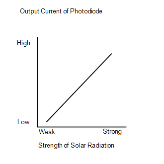
The automatic light control sensor (solar sensor), which is installed on the upper side of the instrument panel, detects sunlight and controls the air conditioning in auto mode. The output current from the automatic light control sensor (solar sensor) varies according to the amount of sunlight. When the amount of sunlight increases, the output current increases. As the amount of sunlight decreases, the output current decreases. The air conditioning amplifier assembly detects the output current from the automatic light control sensor (solar sensor).
|
DTC Code |
DTC Detection Condition |
Trouble Area |
|---|---|---|
|
B14A2 |
An open or short in the driver side solar sensor circuit. |
|
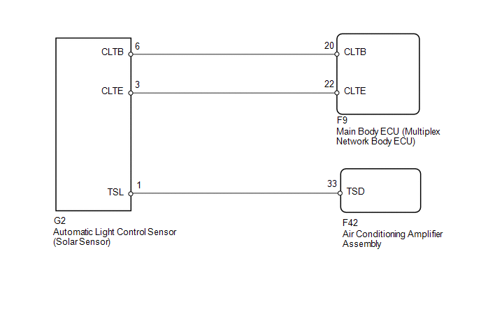
WIRING DIAGRAM
CAUTION / NOTICE / HINT
HINT:
- If DTC B1244 is output together with other DTCs, troubleshoot DTC B1244
first (See page
.gif) ).
). - If the check is performed in a dark place, DTC B14A2 or B14A3 (solar sensor circuit abnormal) may be stored even though the system is normal.
PROCEDURE
|
1. |
READ VALUE USING TECHSTREAM (SOLAR SENSOR) |
(a) Use the Data List to check if the automatic light control sensor (solar sensor)
is functioning properly (See page ).
Air Conditioner
|
Tester Display |
Measurement Item/Range |
Normal Condition |
Diagnostic Note |
|---|---|---|---|
|
Solar Sensor (D side) |
Automatic light control sensor (solar sensor) / Min.: 0, Max.: 255 |
Driver side solar sensor voltage increases as brightness increases |
Open in the circuit: 0. Short in the circuit: 255. |
OK:
The display is as specified in the normal condition column.
Result|
Result |
Proceed to |
|---|---|
|
OK (When troubleshooting according to problem symptoms table) |
A |
|
OK (When troubleshooting according to the DTC) |
B |
|
NG |
C |
| A | .gif) |
PROCEED TO NEXT SUSPECTED AREA SHOWN IN PROBLEM SYMPTOMS TABLE |
| B | |
REPLACE AIR CONDITIONING AMPLIFIER ASSEMBLY |
|
.gif)
|
2. |
CHECK HARNESS AND CONNECTOR (POWER SOURCE CIRCUIT) |
(a) Disconnect the G2 sensor connector.
(b) Measure the voltage according to the value(s) in the table below.
Standard Voltage:
|
Tester Connection |
Switch Condition |
Specified Condition |
|---|---|---|
|
G2-6 (CLTB) - G2-3 (CLTE) |
Ignition switch off |
Below 1 V |
|
G2-6 (CLTB) - G2-3 (CLTE) |
Ignition switch ON |
11 to 14 V |
|
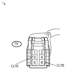
*a |
Front view of wire harness connector (to Automatic Light Control Sensor [Solar Sensor]) |
| NG | |
GO TO STEP 5 |
|
|
3. |
CHECK HARNESS AND CONNECTOR (SOLAR SENSOR - AIR CONDITIONING AMPLIFIER) |
(a) Disconnect the G2 sensor connector.
(b) Disconnect the F42 amplifier connector.
(c) Measure the resistance according to the value(s) in the table below.
Standard Resistance:
|
Tester Connection |
Condition |
Specified Condition |
|---|---|---|
|
G2-1 (TSL) - F42-33 (TSD) |
Always |
Below 1 Ω |
|
G2-1 (TSL) - Body ground |
Always |
10 kΩ or higher |
| NG | |
REPAIR OR REPLACE HARNESS OR CONNECTOR |
|
|
4. |
CHECK AUTOMATIC LIGHT CONTROL SENSOR (SOLAR SENSOR) |
|
(a) Remove the automatic light control sensor (solar sensor) with its
connector still connected (See page |
|
(b) Measure the voltage according to the value(s) in the table below.
Standard Voltage:
|
Tester Connection |
Switch Condition |
Specified Condition |
|---|---|---|
|
G2-1 (TSL) - G2-3 (CLTE) |
Ignition switch ON Sensor subjected to electric light |
0.8 to 4.3 V |
|
G2-1 (TSL) - G2-3 (CLTE) |
Ignition switch ON Sensor covered with cloth |
Below 0.8 V |
|
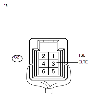
*a |
Component with harness connected (Automatic Light Control Sensor [Solar Sensor]) |
NOTICE:
The connection procedure for using a digital tester such as a TOYOTA electrical tester is shown above. When using an analog tester, connect the negative (-) lead to terminal 1 and the positive (+) lead to terminal 3 of the solar sensor.
HINT:
- Use an incandescent light for inspection. Bring it within about 30 cm (11.8 in.) of the solar sensor.
- As the inspection light is moved away from the sensor, the voltage decreases.
| OK | |
REPLACE AIR CONDITIONING AMPLIFIER ASSEMBLY |
| NG | |
REPLACE AUTOMATIC LIGHT CONTROL SENSOR (SOLAR SENSOR) |
|
5. |
CHECK HARNESS AND CONNECTOR (MAIN BODY ECU - SOLAR SENSOR) |
(a) Disconnect the F9 ECU connector.
(b) Disconnect the G2 sensor connector.
(c) Measure the resistance according to the value(s) in the table below.
Standard Resistance:
|
Tester Connection |
Condition |
Specified Condition |
|---|---|---|
|
F9-22 (CLTE) - G2-3 (CLTE) |
Always |
Below 1 Ω |
|
F9-20 (CLTB) - G2-6 (CLTB) |
Always |
Below 1 Ω |
|
F9-22 (CLTE) - Body ground |
Always |
10 kΩ or higher |
|
F9-20 (CLTB) - Body ground |
Always |
10 kΩ or higher |
| OK | |
REPLACE MAIN BODY ECU (MULTIPLEX NETWORK BODY ECU) |
| NG | |
REPAIR OR REPLACE HARNESS OR CONNECTOR |
 Lost Communication with ECM (U0100,U0142,U0155)
DESCRIPTION
The air conditioning amplifier communicates with the ECM, main body ECU (multiplex
network body ECU) and combination meter through the CAN communication system.
DTC Code
...
 Front Passenger Side Solar Sensor Short Circuit (B14A3)
DESCRIPTION
The automatic light control sensor (solar sensor), which is installed on the
upper side of the instrument panel, detects sunlight and controls the air conditioning
in auto mode. The ...
Other materials about Toyota 4Runner:
Head restraints
Head restraints are provided for all seats.
Adjusting the head restraints
Front and second seats
1. Up Pull the head restraints up.
2. Down Push the head restraint down while pushing the lock release button.
Folding the head restraints
Second seats (ve ...
Dtc Check / Clear
DTC CHECK / CLEAR
CHECK DTC
(a) Connect the Techstream to the DLC3.
(b) Turn the ignition switch to ON.
(c) Turn the Techstream on.
(d) Enter the following menus: Body Electrical / Navigation System / Trouble
Codes.
(e) Check for DTCs (Click here ).
...

0.0066