Toyota 4Runner: Electrical Key Oscillator(for Front Floor)
Components
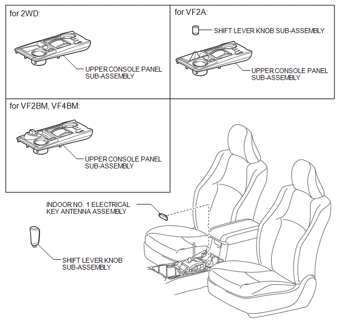
COMPONENTS
ILLUSTRATION
Installation
INSTALLATION
PROCEDURE
1. INSTALL INDOOR NO. 1 ELECTRICAL KEY ANTENNA ASSEMBLY
|
(a) Attach the clamp to install the indoor No. 1 electrical key antenna. |
|
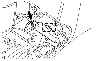
(b) Connect the connector.
2. INSTALL UPPER CONSOLE PANEL SUB-ASSEMBLY
.gif)
3. INSTALL SHIFT LEVER KNOB SUB-ASSEMBLY (for VF2A)
4. INSTALL SHIFT LEVER KNOB SUB-ASSEMBLY
Removal
REMOVAL
PROCEDURE
1. REMOVE SHIFT LEVER KNOB SUB-ASSEMBLY
.gif)
2. REMOVE SHIFT LEVER KNOB SUB-ASSEMBLY (for VF2A)
3. REMOVE UPPER CONSOLE PANEL SUB-ASSEMBLY
4. REMOVE INDOOR NO. 1 ELECTRICAL KEY ANTENNA ASSEMBLY
|
(a) Disconnect the connector. |
|
.png)
(b) Detach the clamp and remove the indoor No. 1 electrical key antenna.
 Removal
REMOVAL
PROCEDURE
1. DISCONNECT CABLE FROM NEGATIVE BATTERY TERMINAL
CAUTION:
Wait at least 90 seconds after disconnecting the cable from the negative (-)
battery terminal to disable the SRS sys ...

Other materials about Toyota 4Runner:
Front Passenger Side Power Window does not Operate with Front Passenger Side
Power Window Switch
DESCRIPTION
If the manual up/down function does not operate, there may be a malfunction
in the power window regulator switch, front power window regulator motor,
harness or connector.
WIRING DIAGRAM
CAUTION / NOTICE / HINT
NOTICE:
I ...
Diagnosis System
DIAGNOSIS SYSTEM
1. SYMPTOM SIMULATION
HINT:
The most difficult case in troubleshooting is when no problem symptoms occur.
In such a case, a thorough problem analysis must be carried out. A simulation of
the same or similar conditions and environment in ...

0.0255