Toyota 4Runner: Removal
REMOVAL
PROCEDURE
1. DISCONNECT CABLE FROM NEGATIVE BATTERY TERMINAL
CAUTION:
Wait at least 90 seconds after disconnecting the cable from the negative (-) battery terminal to disable the SRS system.
NOTICE:
When disconnecting the cable, some systems need to be initialized after the cable
is reconnected (See page .gif) ).
).
2. REMOVE DOOR SCUFF PLATE ASSEMBLY RH
3. REMOVE COWL SIDE TRIM BOARD RH
4. REMOVE NO. 2 INSTRUMENT PANEL UNDER COVER SUB-ASSEMBLY
5. REMOVE LOWER INSTRUMENT COVER LH
6. REMOVE LOWER NO. 2 INSTRUMENT PANEL AIRBAG ASSEMBLY
7. REMOVE INSTRUMENT PANEL BOX DOOR COVER
8. REMOVE LOWER INSTRUMENT PANEL SUB-ASSEMBLY
9. REMOVE NO. 2 AIR DUCT SUB-ASSEMBLY
10. REMOVE ECU INTEGRATION BOX RH
|
(a) Disconnect the connectors and detach the clamp. |
|
.png)
(b) Remove the 2 nuts, bolt and the certification ECU with seat belt control ECU.
11. REMOVE CERTIFICATION ECU
|
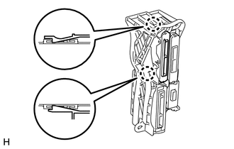
(a) Detach the 2 claws and remove the certification ECU. |
|
 Installation
INSTALLATION
PROCEDURE
1. INSTALL CERTIFICATION ECU
(a) Attach the 2 claws to install the certification ECU.
2. INSTALL ECU INTEGRATION BOX RH
(a) Install the certification ECU with bracket with ...
 Electrical Key Oscillator(for Front Floor)
Components
COMPONENTS
ILLUSTRATION
Installation
INSTALLATION
PROCEDURE
1. INSTALL INDOOR NO. 1 ELECTRICAL KEY ANTENNA ASSEMBLY
(a) Attach the clamp to install the indoor No. 1 ...
Other materials about Toyota 4Runner:
Installation
INSTALLATION
CAUTION / NOTICE / HINT
CAUTION:
Wear protective gloves. Sharp areas on the parts may injure your hands.
HINT:
Use the same procedure for the power seat RH and power seat LH sides.
The procedure listed below is for the power se ...
Voice Recognition Microphone Disconnected (B1579)
DESCRIPTION
The navigation receiver assembly and map light assembly (telephone microphone
assembly) are connected to each other using the microphone connection detection
signal lines.
This DTC is stored when a microphone connection detection signal line ...

0.0234