Toyota 4Runner: Front Blower Motor
Components
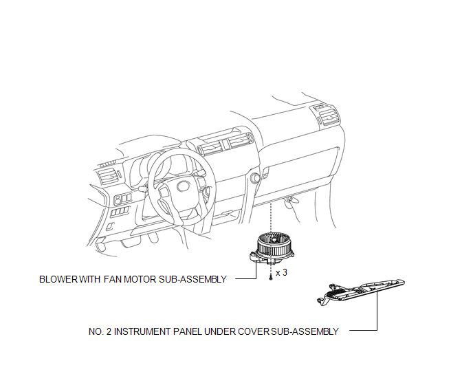
COMPONENTS
ILLUSTRATION
Removal
REMOVAL
PROCEDURE
1. REMOVE NO. 2 INSTRUMENT PANEL UNDER COVER SUB-ASSEMBLY
.gif)
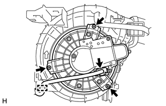
2. REMOVE BLOWER WITH FAN MOTOR SUB-ASSEMBLY
(a) Detach the clamp.
(b) Disconnect the connector.
|
(c) Remove the 3 screws and motor. |
|
Installation
INSTALLATION
PROCEDURE
1. INSTALL BLOWER WITH FAN MOTOR SUB-ASSEMBLY
(a) Install the motor with the 3 screws.
(b) Connect the connector.
(c) Attach the clamp.
2. INSTALL NO. 2 INSTRUMENT PANEL UNDER COVER SUB-ASSEMBLY
.gif)
 Removal
REMOVAL
PROCEDURE
1. DRAIN ENGINE COOLANT
(a) Drain engine coolant (See page ).
2. REMOVE RADIATOR ASSEMBLY
(a) Remove the radiator assembly (See page ).
3. RECOVER REFRIGERANT FROM REFRIGERAT ...

Other materials about Toyota 4Runner:
Removal
REMOVAL
CAUTION / NOTICE / HINT
NOTICE:
Be sure to read PRECAUTION before performing this procedure (See page
).
PROCEDURE
1. REMOVE FRONT WHEEL
2. REMOVE REAR WHEEL
3. REMOVE CENTER CONTROL ABSORBER ASSEMBLY LH
(a) While using a wrench to ...
Portable Player cannot be Operated Using In-vehicle Device or Track Information
is not Displayed on In-vehicle Device
PROCEDURE
1.
CHECK USING ANOTHER "Bluetooth" AUDIO COMPATIBLE VEHICLE OF SAME MODEL
(a) Check if track information is displayed normally on another "Bluetooth" audio
compatible vehicle of the same model.
...

0.0241