Toyota 4Runner: Removal
REMOVAL
PROCEDURE
1. DRAIN ENGINE COOLANT
(a) Drain engine coolant (See page .gif) ).
).
2. REMOVE RADIATOR ASSEMBLY
(a) Remove the radiator assembly (See page ).
3. RECOVER REFRIGERANT FROM REFRIGERATION SYSTEM
4. DISCONNECT DISCHARGE HOSE SUB-ASSEMBLY
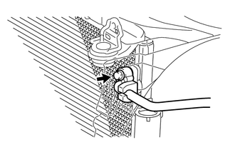
(a) Remove the bolt and disconnect the discharge hose from the cooler condenser.
NOTICE:
- When removing the bolt, do not allow any tools to contact the pipe.
- When removing the bolt, hold a part of the pipe near the connector.
(b) Remove the O-ring from the discharge hose.
NOTICE:
Seal the openings of the disconnected parts using vinyl tape to prevent moisture and foreign matter from entering them.
5. DISCONNECT COOLER REFRIGERANT LIQUID PIPE A
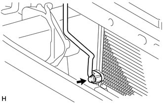
(a) Remove the 2 bolts and disconnect liquid pipe A from the cooler condenser.
NOTICE:
- When removing the bolts, do not allow any tools to contact the pipe.
- When removing the bolts, hold a part of the pipe near the connector.
(b) Remove the O-ring from liquid pipe A.
NOTICE:
Seal the openings of the disconnected parts using vinyl tape to prevent moisture and foreign matter from entering them.
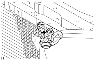
6. DISCONNECT NO. 1 COOLER CONDENSER BRACKET
|
(a) Remove the bolt and disconnect the No. 1 cooler condenser bracket. |
|
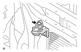
7. DISCONNECT NO. 2 COOLER CONDENSER BRACKET
|
(a) Remove the bolt and disconnect the No. 2 cooler condenser bracket. |
|
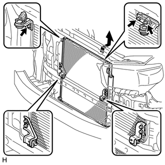
8. REMOVE COOLER CONDENSER ASSEMBLY
|
(a) Remove the 3 bolts and cooler condenser as shown in the illustration. |
|
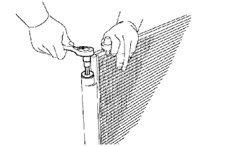
9. REMOVE COOLER DRYER
|
(a) Using a 14 mm socket hexagon wrench, remove the cap from the modulator. |
|
|
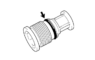
(b) Remove the O-ring from the cap. |
|
|
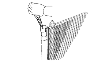
(c) Using pliers, remove the cooler dryer. |
|
 Installation
INSTALLATION
PROCEDURE
1. INSTALL COOLER DRYER
(a) Using pliers, install the cooler dryer.
(b) Apply a sufficient amount of compressor oil to the contact surfaces
of a new O-ring an ...
 Front Blower Motor
Components
COMPONENTS
ILLUSTRATION
Removal
REMOVAL
PROCEDURE
1. REMOVE NO. 2 INSTRUMENT PANEL UNDER COVER SUB-ASSEMBLY
2. REMOVE BLOWER WITH FAN MOTOR SUB-ASSEMBLY
(a) Detach the clam ...
Other materials about Toyota 4Runner:
Reassembly
REASSEMBLY
PROCEDURE
1. INSTALL BACK DOOR UPPER DAMPER STAY BRACKET LH
2. INSTALL BACK DOOR UPPER DAMPER STAY BRACKET RH
HINT:
Use the same procedure as for the LH side.
3. INSTALL BACK DOOR STAY BOLT (for LH Side)
4. INSTALL BACK DOOR STAY BOLT ( ...
Diagnosis System
DIAGNOSIS SYSTEM
1. FUNCTION OF AUTOMATIC RUNNING BOARD WARNING LIGHT
(a) When a malfunction is detected in the automatic running board system, the
automatic running board warning light in the combination meter comes on to inform
the driver of the malfun ...

0.1264