Toyota 4Runner: Back Door Speaker
Components
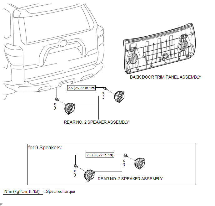
COMPONENTS
ILLUSTRATION
Removal
REMOVAL
CAUTION / NOTICE / HINT
HINT:
- Use the same procedure for the RH and LH sides.
- The procedure listed below is for the LH side.
PROCEDURE
1. DISCONNECT CABLE FROM NEGATIVE BATTERY TERMINAL
NOTICE:
When disconnecting the cable, some systems need to be initialized after the cable
is reconnected (See page .gif) ).
).
2. REMOVE BACK DOOR TRIM PANEL ASSEMBLY
3. REMOVE REAR NO. 2 SPEAKER ASSEMBLY
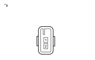
(a) Disconnect the connector.
|
(b) Remove the 3 screws. |
|
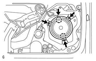
(c) Detach the 2 claws and remove the speaker.
NOTICE:
Do not touch the cone of the speaker.
Inspection
INSPECTION
PROCEDURE
1. INSPECT REAR NO. 2 SPEAKER ASSEMBLY (for 8 Speakers)
|
(a) Measure the resistance according to the value(s) in the table below. Standard Resistance:
|
|
2. INSPECT REAR NO. 2 SPEAKER ASSEMBLY (for 9 Speakers)
(a) Temporarily replace the front No. 2 speaker assembly with a new or normally functioning one.
OK:
Malfunction disappears.
Installation
INSTALLATION
CAUTION / NOTICE / HINT
HINT:
- Use the same procedure for the RH and LH sides.
- The procedure listed below is for the LH side.
PROCEDURE
1. INSTALL REAR NO. 2 SPEAKER ASSEMBLY
(a) Temporarily install the speaker by attaching the 2 claws of the speaker to the door panel.
(b) Install the speaker with the 3 screws.
Torque:
2.5 N·m {25 kgf·cm, 22 in·lbf}
(c) Connect the connector.
NOTICE:
Do not touch the cone of the speaker.
2. INSTALL BACK DOOR TRIM PANEL ASSEMBLY
.gif)
3. CONNECT CABLE TO NEGATIVE BATTERY TERMINAL
NOTICE:
When disconnecting the cable, some systems need to be initialized after the cable
is reconnected (See page ).
 Radio Receiver Power Source Circuit
DESCRIPTION
This is the power source circuit to operate the radio and display receiver assembly.
WIRING DIAGRAM
CAUTION / NOTICE / HINT
NOTICE:
Inspect the fuses for circuits related to this sy ...
 Front Door Speaker
Components
COMPONENTS
ILLUSTRATION
Removal
REMOVAL
CAUTION / NOTICE / HINT
HINT:
Use the same procedure for the RH and LH sides.
The procedure listed below is for the LH side. ...
Other materials about Toyota 4Runner:
Satellite Radio Broadcast cannot be Received
CAUTION / NOTICE / HINT
NOTICE:
Some satellite radio broadcasts require payment. A contract must be
made between a satellite radio company and the user. If the contract expires,
it will not be possible to listen to the broadcast.
PROCE ...
Low Power Supply Voltage Malfunction (C1241)
DESCRIPTION
If the voltage supplied to the IG1 terminal is within the DTC detection range
due to malfunctions in components such as the battery and generator circuit, this
DTC is stored.
DTC Code
DTC Detection Condition
T ...

0.0075