Toyota 4Runner: Horn Circuit
DESCRIPTION
When the theft deterrent system is in the alarm sounding state, the main body ECU outputs a signal repeatedly at 0.4 second intervals, causing the horn(s) to sound.
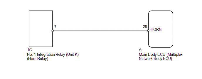
WIRING DIAGRAM
PROCEDURE
|
1. |
CHECK HORN OPERATION |
(a) Press the horn switch and check if the horn(s) sound.
OK:
Horn(s) operate normally.
| NG | .gif) |
GO TO HORN SYSTEM |
|
.gif)
|
2. |
PERFORM ACTIVE TEST USING TECHSTREAM (VEHICLE HORN) |
(a) Operate the Techstream according to the steps on the display and select Active
Test (See page .gif) ).
).
Main Body
|
Tester Display |
Test Part |
Control Range |
Diagnostic Note |
|---|---|---|---|
|
Vehicle Horn |
Vehicle horn(s) |
ON/OFF |
- |
OK:
Horn(s) operate normally.
| OK | |
PROCEED TO NEXT SUSPECTED AREA SHOWN IN PROBLEM SYMPTOMS TABLE |
|
|
3. |
CHECK HARNESS AND CONNECTOR (NO. 1 INTEGRATION RELAY - MAIN BODY ECU) |
(a) Disconnect the 1C relay connector.
(b) Remove the main body ECU (See page ).
(c) Measure the resistance according to the value(s) in the table below.
Standard Resistance:
|
Tester Connection |
Condition |
Specified Condition |
|---|---|---|
|
1C-7 - A-28 (HORN) |
Always |
Below 1 Ω |
|
1C-7 or A-28 (HORN) - Body ground |
Always |
10 kΩ or higher |
| OK | |
REPLACE MAIN BODY ECU (MULTIPLEX NETWORK BODY ECU) |
| NG | |
REPAIR OR REPLACE HARNESS OR CONNECTOR |
 Engine Hood Courtesy Switch Circuit
DESCRIPTION
The security courtesy switch is built into the hood lock. This switch
turns on when the engine hood is opened and turns off when the engine hood
is closed.
WIRING DI ...
 Security Horn Circuit
DESCRIPTION
When the theft deterrent system is in the alarm sounding state, the main body
ECU outputs a signal repeatedly at 0.4 second intervals, causing the security horn
assembly to sound
WIR ...
Other materials about Toyota 4Runner:
Problem Symptoms Table
PROBLEM SYMPTOMS TABLE
HINT:
Use the table below to help determine the cause of problem symptoms.
If multiple suspected areas are listed, the potential causes of the symptoms
are listed in order of probability in the "Suspected Area" ...
No Signal from Transmitter ID1 in Main Mode (C2121/21-C2125/25,C2181/81-C2185/85)
DESCRIPTION
The tire pressure warning valve and transmitters that are installed in the tire
and wheel assemblies measure the tire pressure of the tires. The measured values
are transmitted to the tire pressure warning antenna and receiver on the body as
...

0.0071