Toyota 4Runner: Engine Hood Courtesy Switch Circuit
DESCRIPTION
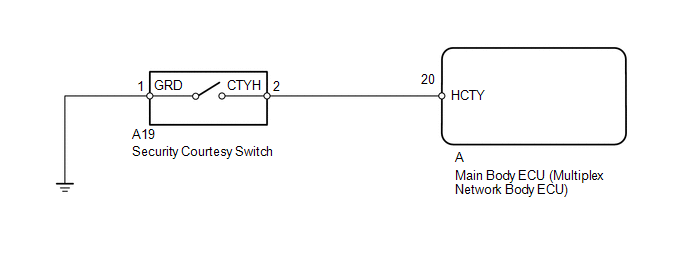
- The security courtesy switch is built into the hood lock. This switch turns on when the engine hood is opened and turns off when the engine hood is closed.
WIRING DIAGRAM
PROCEDURE
|
1. |
READ VALUE USING TECHSTREAM (SECURITY COURTESY SWITCH) |
(a) Using the Techstream, read the Data List (See page
.gif) ).
).
Main Body
|
Tester Display |
Measurement Item/Range |
Normal Condition |
Diagnostic Note |
|---|---|---|---|
|
Hood Courtesy SW |
Security courtesy switch / ON or OFF |
ON: Engine hood open OFF: Engine hood closed |
- |
OK:
ON (engine hood open) and OFF (engine hood closed) appear on screen according to condition of engine hood.
| OK | .gif) |
PROCEED TO NEXT SUSPECTED AREA SHOWN IN PROBLEM SYMPTOMS TABLE |
|
.gif)
|
2. |
INSPECT SECURITY COURTESY SWITCH |
|
(a) Disconnect the A19 switch connector. |
|
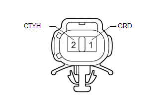
(b) Measure the resistance according to the value(s) in the table below.
Standard Resistance:
|
Tester Connection |
Condition |
Specified Condition |
|---|---|---|
|
1 (GRD) - 2 (CTYH) |
Unlock position |
Below 1 Ω |
|
1 (GRD) - 2 (CTYH) |
Lock position |
10 kΩ or higher |
| NG | |
REPLACE SECURITY COURTESY SWITCH |
|
|
3. |
CHECK HARNESS AND CONNECTOR (SECURITY COURTESY SWITCH - MAIN BODY ECU AND BODY GROUND) |
(a) Disconnect the A19 switch connector.
(b) Remove the main body ECU (See page ).
(c) Measure the resistance according to the value(s) in the table below.
Standard Resistance:
|
Tester Connection |
Condition |
Specified Condition |
|---|---|---|
|
A19-2 (CTYH) - A-20 (HCTY) |
Always |
Below 1 Ω |
|
A19-1 (GRD) - Body ground |
Always |
Below 1 Ω |
|
A19-2 (CTYH) or A-20 (HCTY) - Body ground |
Always |
10 kΩ or higher |
| OK | |
REPLACE MAIN BODY ECU (MULTIPLEX NETWORK BODY ECU) |
| NG | |
REPAIR OR REPLACE HARNESS OR CONNECTOR |
 Data List / Active Test
DATA LIST / ACTIVE TEST
1. DATA LIST
HINT:
Using the Techstream to read the Data List allows the values or states of switches,
sensors, actuators and other items to be read without removing any p ...
 Horn Circuit
DESCRIPTION
When the theft deterrent system is in the alarm sounding state, the main body
ECU outputs a signal repeatedly at 0.4 second intervals, causing the horn(s) to
sound.
WIRING DIAGRAM
...
Other materials about Toyota 4Runner:
Terminals Of Ecm
TERMINALS OF ECM
1. CHECK ECM
HINT:
The standard voltage at each ECM terminal is shown in the table below.
In the table, first follow the information under "Condition". Look under "Terminal
No. (Symbol)" for the terminals to inspect ...
Television Camera(for Rear)
Components
COMPONENTS
ILLUSTRATION
Removal
REMOVAL
PROCEDURE
1. REMOVE ASSIST STRAP HOLE COVER
2. REMOVE ASSIST STRAP ASSEMBLY
3. REMOVE BACK DOOR TRIM PANEL ASSEMBLY
4. REMOVE MULTIPLEX NETWORK DOOR ECU
5. REMOVE NO. 2 BACK DOOR SE ...

0.0067