Toyota 4Runner: Security Horn Circuit
DESCRIPTION
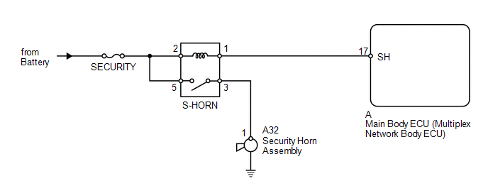
When the theft deterrent system is in the alarm sounding state, the main body ECU outputs a signal repeatedly at 0.4 second intervals, causing the security horn assembly to sound
WIRING DIAGRAM
CAUTION / NOTICE / HINT
NOTICE:
Inspect the fuses for circuits related to this system before performing the following inspection procedure.
PROCEDURE
|
1. |
PERFORM ACTIVE TEST USING TECHSTREAM (SECURITY HORN) |
(a) Operate the Techstream according to the steps on the display and select Active
Test (See page .gif) ).
).
Main Body
|
Tester Display |
Test Part |
Control Range |
Diagnostic Note |
|---|---|---|---|
|
Security Horn |
Security horn |
ON/OFF |
- |
OK:
Security horn operates normally.
| OK | .gif) |
PROCEED TO NEXT SUSPECTED AREA SHOWN IN PROBLEM SYMPTOMS TABLE |
|
.gif)
|
2. |
INSPECT S-HORN RELAY |
|
(a) Remove the S-HORN relay from the engine room relay block. |
|
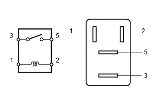
(b) Measure the resistance according to the value(s) in the table below.
Standard Resistance:
|
Tester Connection |
Condition |
Specified Condition |
|---|---|---|
|
3 - 5 |
Battery voltage is not applied to terminals 1 and 2 |
10 kΩ or higher |
|
3 - 5 |
Battery voltage is applied to terminals 1 and 2 |
Below 1 Ω |
| NG | |
REPLACE S-HORN RELAY |
|
|
3. |
INSPECT SECURITY HORN ASSEMBLY |
(a) Remove the security horn (See page ).
(b) Apply battery voltage to the horn connector and check the operation of the horn.
OK:
|
Measurement Condition |
Specified Condition |
|---|---|
|
Battery positive (+) → Terminal 1 Battery negative (-) → Horn bracket |
Horn sounds |
| NG | |
REPLACE SECURITY HORN ASSEMBLY |
|
|
4. |
CHECK HARNESS AND CONNECTOR (ENGINE ROOM RELAY BLOCK - MAIN BODY ECU, SECURITY HORN AND BATTERY) |
(a) Remove the S-HORN relay from the engine room relay block.
(b) Remove the main body ECU (See page ).
(c) Disconnect the A32 horn connector.
(d) Measure the resistance according to the value(s) in the table below.
Standard Resistance:
|
Tester Connection |
Condition |
Specified Condition |
|---|---|---|
|
Relay block S-HORN relay terminal 1 - A-17 (SH) |
Always |
Below 1 Ω |
|
Relay block S-HORN relay terminal 3 - A32-1 |
Always |
Below 1 Ω |
|
A-17 (SH) - Body ground |
Always |
10 kΩ or higher |
|
A32-1 - Body ground |
Always |
10 kΩ or higher |
(e) Measure the voltage according to the value(s) in the table below.
Standard Voltage:
|
Tester Connection |
Condition |
Specified Condition |
|---|---|---|
|
Relay block S-HORN relay terminal 2 - Body ground |
Always |
11 to 14 V |
|
Relay block S-HORN relay terminal 5 - Body ground |
Always |
11 to 14 V |
| OK | |
REPLACE MAIN BODY ECU (MULTIPLEX NETWORK BODY ECU) |
| NG | |
REPAIR OR REPLACE HARNESS OR CONNECTOR |
 Horn Circuit
DESCRIPTION
When the theft deterrent system is in the alarm sounding state, the main body
ECU outputs a signal repeatedly at 0.4 second intervals, causing the horn(s) to
sound.
WIRING DIAGRAM
...
 Security Indicator Light Circuit
DESCRIPTION
When the theft deterrent system is in the disarmed state, the security
indicator light flashes continuously when the engine immobiliser system
is set, and does not illumina ...
Other materials about Toyota 4Runner:
Problem Symptoms Table
PROBLEM SYMPTOMS TABLE
HINT:
Use the table below to help determine the cause of problem symptoms.
If multiple suspected areas are listed, the potential causes of the symptoms
are listed in order of probability in the "Suspected Area" ...
Problem Symptoms Table
PROBLEM SYMPTOMS TABLE
HINT:
Use the table below to help determine the cause of problem symptoms. If multiple
suspected areas are listed, the potential causes of the symptoms are listed in order
of probability in the "Suspected Area" column of ...

0.0065