Toyota 4Runner: IG Power Source Circuit
DESCRIPTION
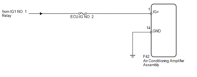
The main power source is supplied to the air conditioning amplifier assembly when the ignition switch is turned to ON. The power source is used for operating the air conditioning amplifier assembly, servo motors, etc.
WIRING DIAGRAM
CAUTION / NOTICE / HINT
NOTICE:
Inspect the fuses for circuits related to this system before performing the following inspection procedure.
HINT:
Start the engine before inspection. Check the relays, fuses and battery if the engine does not start.
PROCEDURE
|
1. |
CHECK HARNESS AND CONNECTOR (AIR CONDITIONING AMPLIFIER - BATTERY AND BODY GROUND) |
|
(a) Disconnect the F42 amplifier connector. |
|
(b) Measure the voltage according to the value(s) in the table below.
Standard Voltage:
|
Tester Connection |
Switch Condition |
Specified Condition |
|---|---|---|
|
F42-1 (IG+) - Body ground |
Ignition switch off |
Below 1 V |
|
Ignition switch ON |
11 to 14 V |
(c) Measure the resistance according to the value(s) in the table below.
Standard Resistance:
|
Tester Connection |
Condition |
Specified Condition |
|---|---|---|
|
F42-14 (GND) - Body ground |
Always |
Below 1 Ω |
|
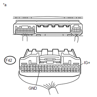
*a |
Rear view of wire harness connector (to Air Conditioning Amplifier Assembly) |
| OK | .gif) |
PROCEED TO NEXT SUSPECTED AREA SHOWN IN PROBLEM SYMPTOMS TABLE |
| NG | |
REPAIR OR REPLACE HARNESS OR CONNECTOR |
 PTC Heater Circuit
DESCRIPTION
PTC heater relays are closed in accordance with signals from the air conditioning
amplifier assembly and power is supplied to the quick heater assembly installed
on the radiator heate ...
 Back-up Power Source Circuit
DESCRIPTION
The back-up power source circuit for the air conditioning amplifier assembly
is shown below. Power is supplied even after the ignition switch is turned off and
is used for diagnostic ...
Other materials about Toyota 4Runner:
Rear Door LH ECU Communication Stop (B2324)
DESCRIPTION
This DTC is stored when LIN communication between the rear power window regulator
motor assembly LH and main body ECU (multiplex network body ECU) stops for 10 seconds
or more.
DTC Code
DTC Detection Condition
...
Removal
REMOVAL
CAUTION / NOTICE / HINT
CAUTION:
Wear protective gloves. Sharp areas on the parts may injure your hands.
HINT:
The procedure listed below is for the RH side.
PROCEDURE
1. PRECAUTION
CAUTION:
Be sure to read Precaution thoroughly before ...

0.0066