
Toyota 4Runner: Removal
REMOVAL
CAUTION / NOTICE / HINT
CAUTION:
Wear protective gloves. Sharp areas on the parts may injure your hands.
HINT:
The procedure listed below is for the RH side.
PROCEDURE
1. PRECAUTION
CAUTION:
- Be sure to read Precaution thoroughly before servicing (See page
.gif) ).
). - If the side airbag was deployed, replace the separate type front seatback assembly with the necessary parts in accordance with the extent of the collision damage.
2. DISCONNECT CABLE FROM NEGATIVE BATTERY TERMINAL
CAUTION:
Wait at least 90 seconds after disconnecting the cable from the negative (-) battery terminal to disable the SRS system.
NOTICE:
When disconnecting the cable, some systems need to be initialized after the cable
is reconnected (See page ).
3. REMOVE FRONT SEAT HEADREST ASSEMBLY
(a) Remove the front seat headrest assembly.
4. REMOVE FRONT SEAT INNER TRACK BRACKET COVER RH
(a) Operate the seat track adjusting handle to move the front seat assembly to the rearmost position.
|
(b) Using a moulding remover, detach the 2 claws. |
|
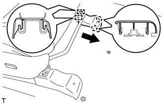
(c) Move the front seat inner track bracket cover RH in the direction of the arrow to detach the 2 guides and remove the front seat inner track bracket cover RH.
5. REMOVE FRONT SEAT OUTER TRACK BRACKET COVER RH
|
(a) Using a moulding remover, detach the 2 claws. |
|
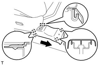
(b) Move the front seat outer track bracket cover RH in the direction of the arrow to detach the 2 claws and guide and remove the front seat outer track bracket cover RH.
6. REMOVE INNER SEAT TRACK BRACKET COVER RH
(a) Operate the seat track adjusting handle to move the front seat assembly to the foremost position.
|
(b) Using a moulding remover, detach the 2 claws. |
|
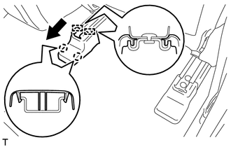
(c) Move the inner seat track bracket cover RH in the direction of the arrow to detach the 2 guides and remove the inner seat track bracket cover RH.
7. REMOVE OUTER SEAT TRACK COVER RH
|
(a) Using a moulding remover, detach the 2 claws. |
|
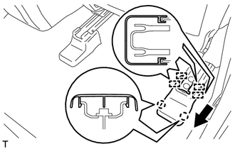
(b) Move the outer seat track cover RH in the direction of the arrow to detach the 4 guides and remove the outer seat track cover RH.
8. REMOVE FRONT SEAT ASSEMBLY
|
(a) Remove the 2 bolts. |
|
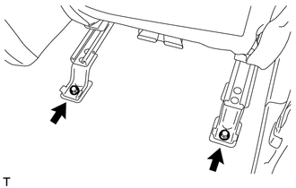
(b) Operate the seat track adjusting handle to move the front seat assembly to the rearmost position.
|
(c) Remove the 2 bolts. |
|
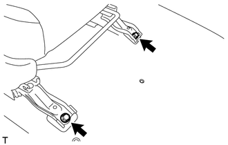
(d) Operate the seat track adjusting handle to move the front seat assembly to the center position, and operate the reclining adjuster release handle RH and move the seatback to the upright position.
(e) Disconnect the connectors under the seat.
(f) Remove the front seat assembly.
NOTICE:
Be careful not to damage the vehicle body.
 Components
COMPONENTS
ILLUSTRATION
ILLUSTRATION
ILLUSTRATION
ILLUSTRATION
ILLUSTRATION
...
 Installation
INSTALLATION
CAUTION / NOTICE / HINT
CAUTION:
Wear protective gloves. Sharp areas on the parts may injure your hands.
HINT:
The procedure listed below is for the RH side.
PROCEDURE
1. INSTALL F ...
Other materials about Toyota 4Runner:
Installation
INSTALLATION
PROCEDURE
1. INSTALL BRAKE BOOSTER GASKET
(a) Install a new brake booster gasket to the hydraulic brake booster.
2. INSTALL HYDRAULIC BRAKE BOOSTER ASSEMBLY
(a) Install the hydraulic brake booster assembly with the 4 nuts.
Torque:
14 N·m ...
Operation Check
OPERATION CHECK
1. NOTICES WHEN CHECKING
(a) Wireless door lock/unlock function:
This function operates only when the vehicle is in its initial condition (the
following 3 conditions are met).
No key is inserted into the ignition key cylinder.
...

0.0268