Toyota 4Runner: Rear Door LH ECU Communication Stop (B2324)
DESCRIPTION
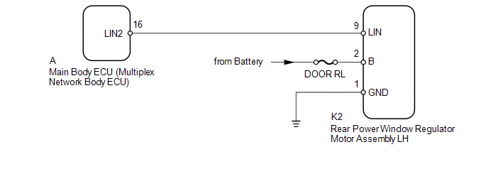
This DTC is stored when LIN communication between the rear power window regulator motor assembly LH and main body ECU (multiplex network body ECU) stops for 10 seconds or more.
|
DTC Code |
DTC Detection Condition |
Trouble Area |
|---|---|---|
|
B2324 |
No communication between the rear power window regulator motor assembly LH and main body ECU (multiplex network body ECU) for 10 seconds or more. |
|
WIRING DIAGRAM
CAUTION / NOTICE / HINT
NOTICE:
- When using the Techstream with the ignition switch off to troubleshoot:
Connect the Techstream to the vehicle and turn a courtesy light switch on and off at 1.5 second intervals until communication between the Techstream and vehicle begins.
- Inspect the fuses and bulbs for circuits related to this system before performing the following inspection procedure.
HINT:
When communication between the rear power window regulator motor assembly LH and main body ECU (multiplex network body ECU) stops, DTC B2325 is also stored.
PROCEDURE
|
1. |
CLEAR DTC |
(a) Clear the DTCs (See page .gif) ).
).
|
.gif)
|
2. |
CHECK FOR DTC |
(a) Check for DTCs (See page ).
OK:
DTC B2324 is not output.
| OK | .gif) |
USE SIMULATION METHOD TO CHECK |
|
|
3. |
CHECK HARNESS AND CONNECTOR (MAIN BODY ECU - REAR POWER WINDOW REGULATOR MOTOR LH) |
(a) Remove the main body ECU (multiplex network body ECU) from the driver side
junction block assembly (See page ).
(b) Disconnect the K2 rear power window regulator motor assembly LH connector.
(c) Measure the resistance according to the value(s) in the table below.
Standard Resistance:
|
Tester Connection |
Condition |
Specified Condition |
|---|---|---|
|
A-16 (LIN2) - K2-9 (LIN) |
Always |
Below 1 Ω |
|
A-16 (LIN2) or K2-9 (LIN) - Body ground |
Always |
10 kΩ or higher |
| NG | |
REPAIR OR REPLACE HARNESS OR CONNECTOR |
|
|
4. |
CHECK HARNESS AND CONNECTOR (REAR POWER WINDOW REGULATOR MOTOR LH - BATTERY AND BODY GROUND) |
|
(a) Disconnect the K2 rear power window regulator motor assembly LH connector. |
|
(b) Measure the resistance according to the value(s) in the table below.
Standard Resistance:
|
Tester Connection |
Condition |
Specified Condition |
|---|---|---|
|
K2-1 (GND) - Body ground |
Always |
Below 1 Ω |
(c) Measure the voltage according to the value(s) in the table below.
Standard Voltage:
|
Tester Connection |
Condition |
Specified Condition |
|---|---|---|
|
K2-2 (B) - Body ground |
Always |
11 to 14 V |
|
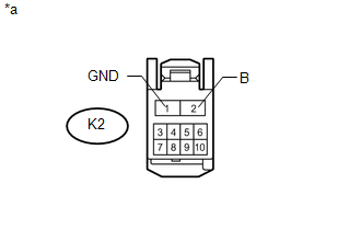
*a |
Front view of wire harness connector (to Rear Power Window Regulator Motor Assembly LH) |
| NG | |
REPAIR OR REPLACE HARNESS OR CONNECTOR |
|
|
5. |
REPLACE REAR POWER WINDOW REGULATOR MOTOR ASSEMBLY LH |
(a) Temporarily replace the rear power window regulator motor assembly LH with
a new or normally functioning one (See page ).
|
|
6. |
CLEAR DTC |
(a) Clear the DTCs (See page ).
|
|
7. |
CHECK FOR DTC |
(a) Check for DTCs (See page ).
OK:
DTC B2324 is not output.
| OK | |
END (REAR POWER WINDOW REGULATOR MOTOR LH IS DEFECTIVE) |
| NG | |
REPLACE MAIN BODY ECU (MULTIPLEX NETWORK BODY ECU) |
 Lost Communication with Back Door Power Window ECU (Abnormal Power Supply) (B2327,B2328)
DESCRIPTION
DTC B2327 is stored when LIN communication between the multiplex network
door ECU (back door P/W) and back door power window regulator motor assembly
stops for 10 seconds o ...
 LIN Communication Master Malfunction (B2287,B278C)
DESCRIPTION
DTC B2287 is stored when there is an open or short circuit or an ECU
communication malfunction between the power management control ECU and certification
ECU.
DTC B278C ...
Other materials about Toyota 4Runner:
Adjusting the position of and opening and closing the air outlets
Front center outlets
1. Direct air flow to the left or right, up or down.
2. Turn the knob to open or close the vent.
Front side outlets
1. Direct air flow to the left or right, up or down.
2. Turn the knob to open or close the vent.
Rear outlets
...
On-vehicle Inspection
ON-VEHICLE INSPECTION
PROCEDURE
1. CHECK STEERING PAD (VEHICLE NOT INVOLVED IN COLLISION)
(a) Perform a diagnostic system check (See page
).
(b) With the steering pad installed on the vehicle, perform a visual check. If
there are any defects as mention ...

0.1537