Toyota 4Runner: Ignition Key Cylinder Light
Components
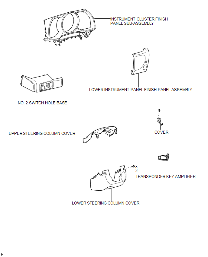
COMPONENTS
ILLUSTRATION
Removal
REMOVAL
PROCEDURE
1. REMOVE NO. 2 SWITCH HOLE BASE
.gif)
2. REMOVE LOWER INSTRUMENT PANEL FINISH PANEL ASSEMBLY
3. REMOVE INSTRUMENT CLUSTER FINISH PANEL SUB-ASSEMBLY
4. REMOVE LOWER STEERING COLUMN COVER
5. REMOVE UPPER STEERING COLUMN COVER
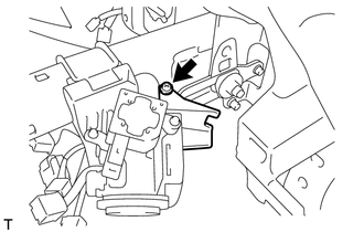
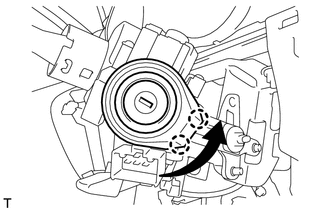
6. REMOVE TRANSPONDER KEY AMPLIFIER
|
(a) Remove the screw and cover. |
|
|
(b) Turn the key amplifier as shown in the illustration to detach the 2 claws and remove the key amplifier. |
|
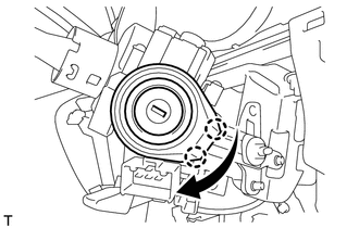
(c) Disconnect the connector.
Inspection
INSPECTION
PROCEDURE
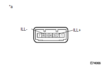
1. INSPECT TRANSPONDER KEY AMPLIFIER
|
(a) Apply battery voltage to the connector and check the LED illumination. OK:
If the result is not as specified, replace the transponder key amplifier. Text in Illustration
|
|
Installation
INSTALLATION
PROCEDURE
1. INSTALL TRANSPONDER KEY AMPLIFIER
|
(a) Connect the connector. |
|
(b) Turn the key amplifier as shown in the illustration to attach the 2 claws and install the key amplifier.
(c) Install the cover with the screw.
2. INSTALL UPPER STEERING COLUMN COVER
.gif)
3. INSTALL LOWER STEERING COLUMN COVER
4. INSTALL INSTRUMENT CLUSTER FINISH PANEL SUB-ASSEMBLY
5. INSTALL LOWER INSTRUMENT PANEL FINISH PANEL ASSEMBLY
6. INSTALL NO. 2 SWITCH HOLE BASE
 Front Door Courtesy Switch
Components
COMPONENTS
ILLUSTRATION
Inspection
INSPECTION
PROCEDURE
1. INSPECT FRONT DOOR COURTESY LIGHT SWITCH ASSEMBLY
(a) Measure the resistance according to the value(s) in ...
 Lighting System
...
Other materials about Toyota 4Runner:
Removal
REMOVAL
PROCEDURE
1. DISCONNECT CABLE FROM NEGATIVE BATTERY TERMINAL
CAUTION:
Wait at least 90 seconds after disconnecting the cable from the negative (-)
battery terminal to disable the SRS system.
NOTICE:
When disconnecting the cable, some systems ne ...
Precaution
PRECAUTION
1. IGNITION SWITCH EXPRESSIONS
HINT:
The type of ignition switch used on this model differs according to the specifications
of the vehicle. The expressions listed in the table below are used in this section.
Expression
Ig ...

0.0265