Toyota 4Runner: Front Door Courtesy Switch
Components
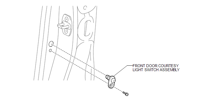
COMPONENTS
ILLUSTRATION
Inspection
INSPECTION
PROCEDURE
1. INSPECT FRONT DOOR COURTESY LIGHT SWITCH ASSEMBLY
|
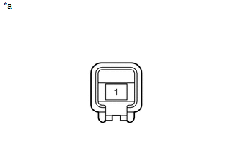
(a) Measure the resistance according to the value(s) in the table below. Standard Resistance:
If the result is not as specified, replace the front door courtesy light switch assembly. Text in Illustration
|
|
Removal
REMOVAL
CAUTION / NOTICE / HINT
HINT:
- Use the same procedure for the RH and LH sides.
- The procedure listed below is for the LH side.
PROCEDURE
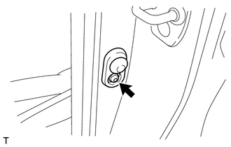
1. REMOVE FRONT DOOR COURTESY LIGHT SWITCH ASSEMBLY
|
(a) Using a T30 "TORX" socket wrench, remove the screw and courtesy light switch. |
|
(b) Disconnect the connector.
Installation
INSTALLATION
CAUTION / NOTICE / HINT
HINT:
- Use the same procedure for the RH and LH sides.
- The procedure listed below is for the LH side.
PROCEDURE
1. INSTALL FRONT DOOR COURTESY LIGHT SWITCH ASSEMBLY
(a) Connect the connector.
(b) Using a T30 "TORX" socket wrench, install the courtesy light switch with the screw.
 Door Courtesy Light(for Rear Door)
Components
COMPONENTS
ILLUSTRATION
Removal
REMOVAL
CAUTION / NOTICE / HINT
HINT:
Use the same procedure for the RH and LH sides.
The procedure listed below is for the LH side. ...
 Ignition Key Cylinder Light
Components
COMPONENTS
ILLUSTRATION
Removal
REMOVAL
PROCEDURE
1. REMOVE NO. 2 SWITCH HOLE BASE
2. REMOVE LOWER INSTRUMENT PANEL FINISH PANEL ASSEMBLY
3. REMOVE INSTRUMENT CLUSTER FI ...
Other materials about Toyota 4Runner:
VSC OFF Indicator Light does not Come ON
DESCRIPTION
Refer to VSC OFF Indicator Light Remains ON (See page
).
WIRING DIAGRAM
Refer to VSC OFF Indicator Light Remains ON (See page
).
CAUTION / NOTICE / HINT
NOTICE:
When replacing the master cylinder solenoid, perform calibration (See page
...
Installation
INSTALLATION
PROCEDURE
1. INSTALL INSTRUMENT PANEL PASSENGER AIRBAG ASSEMBLY
(a) Attach the 5 hooks (A).
Text in Illustration
*a
Hook A
*b
Hook B
...

0.0064